

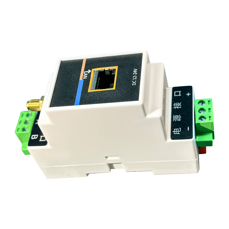
Why Environmental Monitoring Has Become a Core Reliability Function
Unplanned downtime in manufacturing plants, data centers, and process facilities rarely originates from a single dramatic failure. In most cases, it begins with a small deviation: a bearing that runs slightly hotter than normal, a gas line that loses flow consistency, or a control cabinet that drifts outside its rated temperature range. An industrial temperature monitoring system built on connected sensors and transmitters is designed to catch these deviations long before they become failures.
Traditional monitoring relied on scheduled manual checks using handheld instruments. This approach leaves long gaps between readings, and by the time an inspector notices a problem, the equipment may already be operating in a degraded state. Real-time temperature monitoring closes that gap by streaming continuous data from the field to a central platform, allowing operations teams to respond within minutes instead of days.
Facilities that shift from periodic manual inspection to continuous IoT-based monitoring typically identify abnormal thermal or vibration trends three to five times earlier than manual rounds alone.
Core Architecture of an IoT Environmental Monitoring System
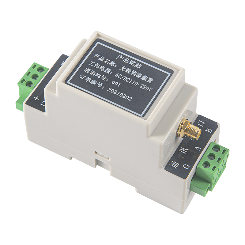
A functional monitoring architecture is built in layers, each responsible for a specific task: sensing the physical condition, transmitting the signal, processing the data, and presenting actionable information to the operator.
Each layer must be reliable independently, because a weak link at any stage undermines the accuracy of the entire chain. A well-designed wireless sensor network reduces cabling costs and simplifies deployment across large facilities, while transmitters standardize the signal so that data acquisition systems can interpret it consistently regardless of sensor type.
Wireless Sensing for Rotating and Critical Equipment
Rotating machinery such as motors, pumps, fans, and compressors is one of the most common sources of unplanned downtime. Two physical indicators tend to change together as a mechanical fault develops: surface or bearing temperature, and vibration amplitude across specific frequency bands. Monitoring both parameters from a single mounting point gives a more complete picture than tracking either one alone.
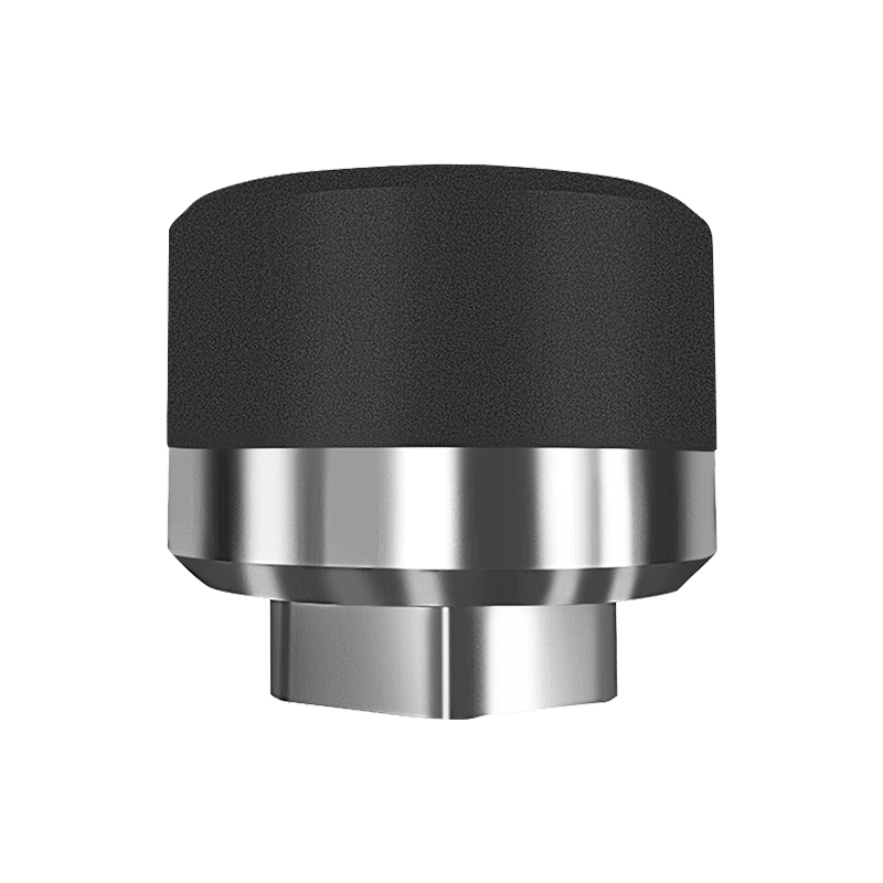
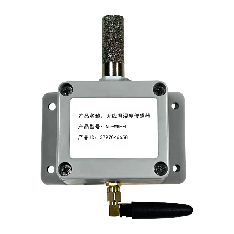
A wireless temperature and vibration integrated sensor combines both measurement functions in a compact housing that can be mounted directly on bearing housings, motor frames, or gearboxes without additional wiring runs. This reduces installation labor significantly compared with running separate cable pairs for each measurement type, which matters most in facilities with hundreds of monitoring points spread across large physical footprints.
| Fault Indicator | Typical Early Sign | Detection Value |
|---|---|---|
| Bearing wear | Gradual temperature rise plus high-frequency vibration | Weeks of advance warning |
| Shaft misalignment | Elevated vibration at running speed frequency | Days to weeks |
| Imbalance | Vibration amplitude increase at one times running speed | Days to weeks |
| Lubrication loss | Rapid temperature increase with minor vibration change | Hours to days |
Measuring Gas Flow with Thermal Mass Flow Technology
Environmental monitoring is not limited to temperature and vibration. In facilities that handle compressed air, combustion air, natural gas, or process gases, flow measurement accuracy directly affects energy efficiency and safety compliance. Traditional differential pressure flow meters require additional components and lose accuracy at low flow rates, which makes them less suitable for environments with variable demand.
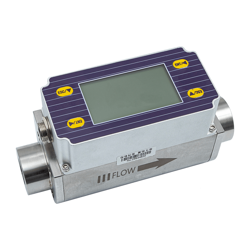
A thermal gas mass flow meter (tmf) measures flow based on the heat transfer rate between two temperature sensing elements, providing a direct mass flow reading without needing separate pressure and temperature compensation. This design tends to maintain accuracy across a wider flow range, which is particularly useful for monitoring compressed air leaks, ventilation systems, and gas distribution networks where flow rates fluctuate throughout a production cycle.
- Direct mass flow output without additional pressure or density correction
- Stable readings across low and high flow conditions
- No moving parts, reducing mechanical wear and maintenance frequency
- Suitable for integration into existing IoT environmental monitoring networks
The Role of Industrial Transmitters in Signal Integrity
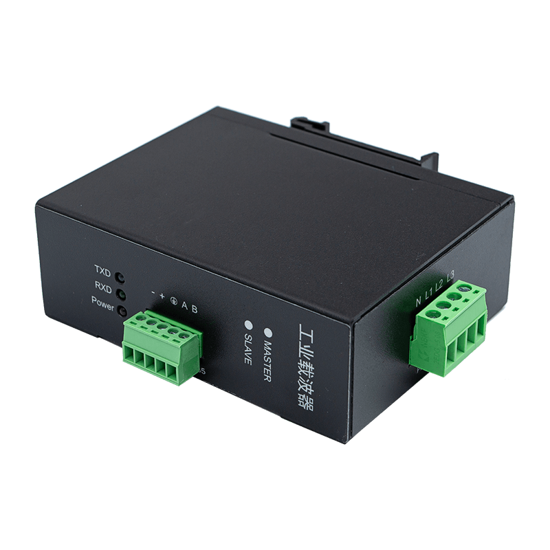
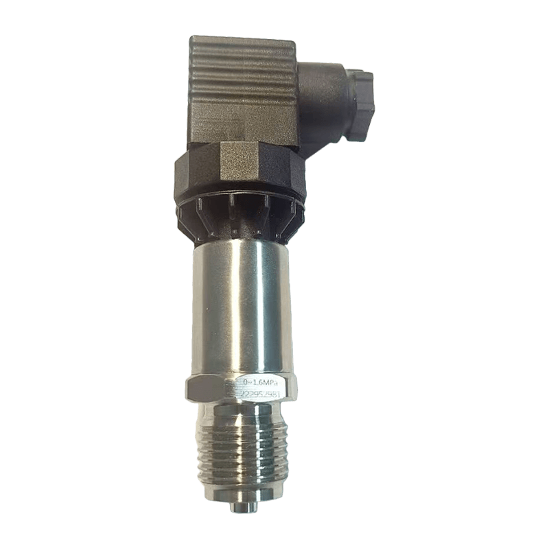
Sensors generate raw physical signals, but these signals are often weak, susceptible to electrical noise, or incompatible with the communication protocols used by data acquisition systems. This is where transmitters become essential. They convert raw sensor output into standardized signals such as current loops or digital protocols that can travel longer distances without signal degradation.
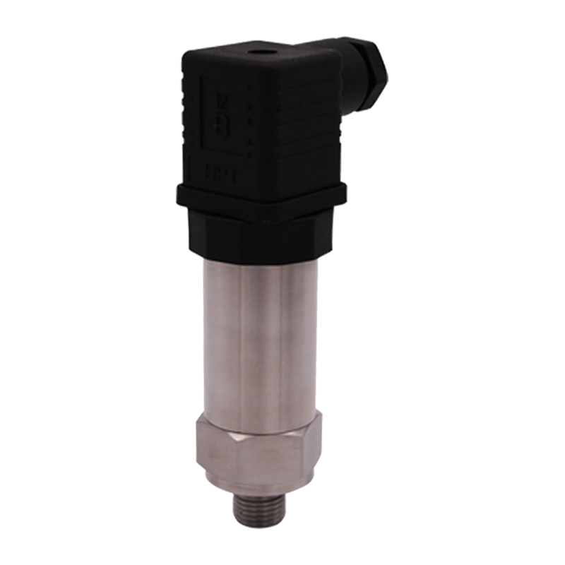
Reliable industrial transmitters also perform signal conditioning tasks such as linearization, filtering, and cold junction compensation for thermocouple inputs. In multi-sensor environments, transmitters act as the translation layer that allows different sensor types, whether thermal, vibration, pressure, or flow, to feed a common monitoring platform using a consistent data format.
Applying Environmental Monitoring to Server Room Conditions
Data centers and server rooms present a distinct monitoring challenge because thermal conditions can vary significantly between rack rows, and even small temperature gradients affect equipment lifespan. Server room monitoring typically requires multiple distributed sensor points rather than a single central reading, since hot spots often form near high-density racks or blocked airflow paths.
| Monitoring Zone | Primary Parameter | Recommended Interval |
|---|---|---|
| Cold aisle intake | Ambient temperature | 1 to 5 minutes |
| Hot aisle exhaust | Ambient temperature and airflow | 1 to 5 minutes |
| Rack top and bottom | Vertical temperature gradient | 5 minutes |
| Humidity control zone | Relative humidity | 5 to 10 minutes |
Because server rooms operate continuously, sensors deployed for this purpose need stable long term accuracy and low drift, since recalibration downtime is difficult to schedule without affecting operations.
Building a Dependable Remote Monitoring Platform
Collecting field data is only half the task. A remote monitoring platform needs to store historical data, apply threshold logic, and notify the right personnel when a reading moves outside an acceptable range. Several design factors determine whether a platform will hold up under real operating conditions.
Data Reliability
Local buffering at the gateway level ensures that brief network interruptions do not result in permanent data loss. Once connectivity is restored, buffered readings should sync automatically to preserve a continuous historical record.
Alert Logic
Static thresholds are useful for hard safety limits, but many facilities benefit from trend-based alerts that flag gradual drift even before a fixed threshold is crossed. This is where predictive analytics adds value beyond simple pass or fail notifications.
Scalability
As facilities add monitoring points over time, the platform architecture should support incremental scaling without requiring a redesign of the network topology or data model.
From Raw Telemetry to Predictive Maintenance
Raw data alone does not prevent failures; it is the analysis layer that converts telemetry into a maintenance action. The workflow below outlines how continuous monitoring typically feeds into a preventive maintenance program.
This structured flow supports preventive maintenance planning by giving maintenance teams a data-backed reason to intervene, rather than relying on fixed calendar intervals that either replace healthy components too early or miss failing ones entirely.
Practical Deployment Considerations
- Map critical assets first and prioritize monitoring points based on failure impact rather than convenience of installation
- Select sensor sampling rates that match the speed at which the monitored condition can change
- Plan wireless network coverage around physical obstructions such as metal enclosures and thick walls
- Establish a data retention policy that balances storage cost against the need for long-term trend analysis
- Define escalation rules so alerts reach the correct team without generating alert fatigue
These steps apply equally whether the deployment covers a single production line or a multi-building industrial campus. Equipment reliability improves most when monitoring data is paired with a clear response process, not just visibility alone.
Frequently Asked Questions
Q1: How often should industrial sensors report data for effective monitoring?
Reporting frequency depends on how quickly the monitored condition can change. Rotating equipment vibration may need readings every few seconds, while ambient temperature in a stable environment can often be sampled every few minutes without losing useful detail.
Q2: Can wireless sensors replace all wired monitoring instrumentation?
Wireless sensors work well for distributed points where cabling is impractical, but wired connections may still be preferred for safety-critical shutdown functions that require guaranteed signal continuity.
Q3: What causes inaccurate readings in an IoT monitoring network?
Common causes include poor sensor placement, electrical interference affecting signal transmission, insufficient transmitter calibration, and gateway connectivity gaps that create data blind spots.
Q4: How does thermal mass flow measurement differ from pressure-based flow measurement?
Thermal mass flow measurement reads flow directly through heat transfer principles, while pressure-based methods infer flow indirectly and typically require separate temperature and pressure compensation for accuracy.
Q5: What is the first step in setting up an environmental monitoring program?
The first step is identifying which assets or zones carry the highest operational or safety risk, since this determines where sensors and transmitters should be prioritized before broader network expansion.