

Why Differential Pressure Measurement Anchors Modern Process Control
Every ventilation system, filtration line, and process vessel depends on a pressure balance that most operators never see directly. That balance is tracked through differential pressure readings taken between two points in a duct, pipe, or chamber. When the gap between those two points shifts even slightly, it signals a clogged filter, a leaking duct, a failing fan, or a contamination risk long before the problem becomes visible to the naked eye.
industrial transmitters built for this task translate a physical force into a usable electronic signal, giving building managers and plant engineers a continuous, real-time view of conditions that would otherwise require manual gauge checks. In facilities where airflow direction and pressure containment are safety-critical, such as hospitals, laboratories, and semiconductor plants, this continuous monitoring is not optional. It is the backbone of compliance reporting and operational safety.
The demand for reliable differential pressure data spans far beyond HVAC. Dust collection systems use it to detect filter loading. Cleanrooms use it to confirm directional airflow. Fume hoods use it to verify containment. Data centers use it to manage hot aisle and cold aisle separation. Across all of these applications, the underlying measurement principle is the same, even though the instruments, ranges, and mounting methods vary considerably.
A pressure differential of just a few hundredths of an inch of water column can determine whether a cleanroom holds its classification or fails an audit, which is why measurement resolution matters as much as measurement range.
How Do Differential Pressure Transmitters Work
At the core of every pressure transmitter is a sensing element, most commonly a diaphragm, that physically separates a high-pressure port from a low-pressure port. Gas or air enters both ports through separate tubing runs connected to different points in the system being measured. The diaphragm flexes in proportion to the force difference between the two sides.
That mechanical deflection is converted into an electrical signal through one of a few common technologies:
- Capacitive sensing, where diaphragm movement changes the capacitance between the diaphragm and a fixed plate
- Piezoresistive sensing, where strain on a silicon element changes its electrical resistance
- Variable reluctance sensing, used in some legacy and ruggedized designs for harsh environments
The resulting signal is then conditioned and scaled by onboard electronics into a standardized output, typically 4 to 20 milliamps, 0 to 10 volts, or a digital protocol such as Modbus. That output feeds a building automation system, a programmable logic controller, or a standalone display, allowing the raw pressure difference to be logged, trended, and alarmed against a setpoint.
DP Cells and Pressure Transmitter Accessories Explained
The term dp cell refers to the sensing capsule inside the transmitter housing, but a complete measurement loop rarely relies on the sensor alone. Field installations typically add a set of supporting accessories that protect the sensing element and improve reading stability over the life of the installation.
| Accessory | Function | Typical Use Case |
|---|---|---|
| Static pressure probes | Sample air pressure at a single duct point | Duct static pressure control loops |
| Sensing tubing kits | Route pressure signal from tap point to transmitter | Remote-mounted transmitters |
| Snubbers | Dampen pressure spikes and pulsation | Pump and compressor discharge lines |
| Manifold valves | Isolate, equalize, and vent the sensor for service | Process plants requiring in-service calibration |
| Weatherproof enclosures | Shield electronics from moisture and dust | Rooftop and outdoor air handling units |
Choosing the right combination of accessories has a direct effect on long-term accuracy. A transmitter with an undersized sensing tube, for example, can introduce lag into fast-changing pressure readings, while a poorly filtered air intake can allow particulate to foul the diaphragm over time. In dusty or humid environments, adding an inline filter and a drip leg to the sensing tubing is a low-cost way to extend service intervals significantly.
Where Air Differential Pressure Transmitters Are Applied
An air differential pressure transmitter earns its keep across a wide range of building and process environments, each with different tolerance for error and different consequences for drift.
Cleanroom Pressure Monitoring
Cleanrooms rely on a cascading pressure hierarchy, where each zone is held slightly more positive or negative than its neighbor to control particle migration. Typical target differentials fall in the range of a few hundredths to a tenth of an inch of water column between adjacent rooms. A transmitter used here needs fine resolution and low drift, since even a small offset can allow contaminants to migrate against the intended airflow direction.
HVAC Pressure Sensors in Building Automation
In commercial buildings, hvac pressure sensors regulate variable air volume boxes, control fan speed through duct static pressure resets, and confirm that return air paths are not restricted. These readings feed directly into energy management strategies, since running a fan harder than necessary to overcome an undetected restriction wastes a measurable amount of electricity over a full operating year.
Negative Pressure Sensor Applications
A negative pressure sensor is used wherever containment matters more than comfort, such as isolation rooms, fume hoods, and biosafety cabinets. These applications typically pair the transmitter with a visual or audible alarm that triggers if the room pressure drifts toward neutral or positive, since that shift indicates a potential breach of containment.
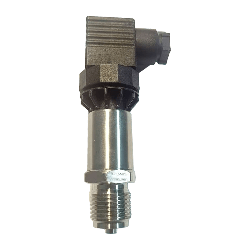
Industrial pressure sensors used outside of building environments, such as on baghouse filters, boiler draft controls, and compressor intake lines, face additional demands from temperature extremes, vibration, and corrosive atmospheres. These installations often specify heavier housings, wider operating temperature ratings, and remote diaphragm seals to keep the sensing element isolated from harsh process media.
Thermal Gas Mass Flow Meter Technology for Gas Flow Verification
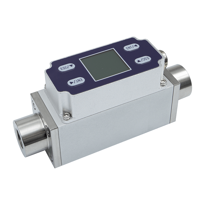
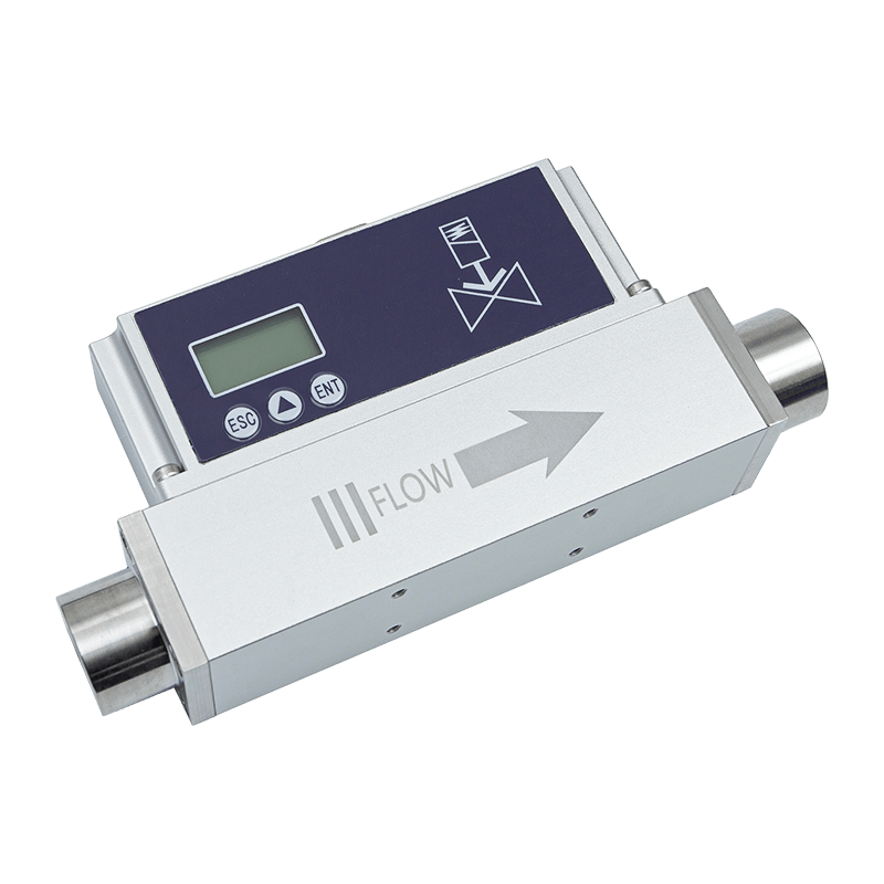
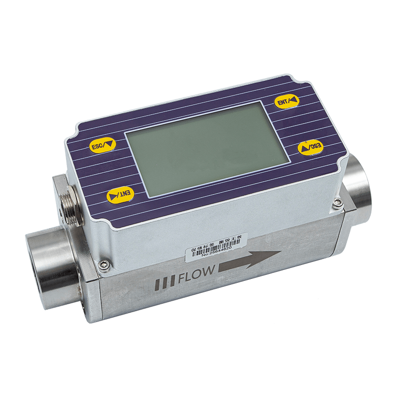
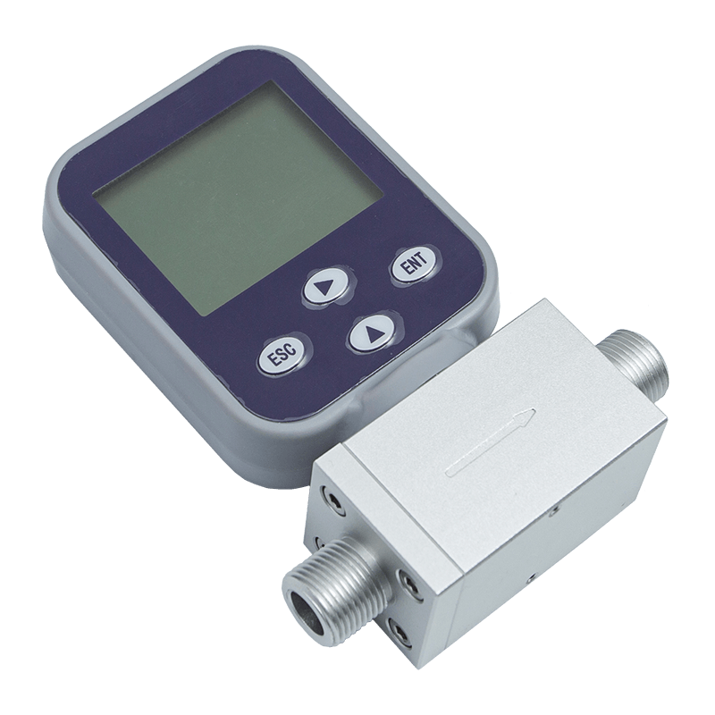
While differential pressure transmitters measure a pressure difference, a thermal gas mass flow meter (tmf) measures gas flow directly by mass rather than by volume. This distinction matters in applications where gas density changes with temperature or pressure, since a volumetric reading alone can misrepresent the actual quantity of gas moving through a line.
A thermal mass flow meter typically uses two temperature sensing elements positioned in the gas stream. One element is heated to a constant temperature above the gas stream, while the other measures the ambient gas temperature. As gas flows past the heated element, it carries heat away at a rate proportional to the mass flow rate. The meter measures the power needed to maintain the heated element at its setpoint, and that power draw is translated directly into a mass flow reading.
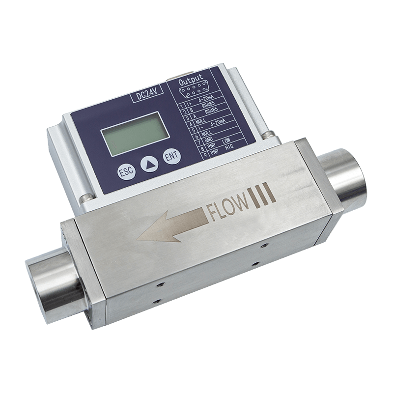
Because thermal mass flow meters do not require separate temperature and pressure compensation to report a true mass value, they are widely used for combustion air monitoring, natural gas measurement, compressed air auditing, and biogas flow verification in wastewater treatment. Their lack of moving parts also reduces the maintenance burden compared with mechanical flow meters, though the sensing elements still benefit from periodic cleaning in dusty or oily gas streams.
Selecting Between Differential Pressure and Thermal Mass Flow Instruments
Deciding which instrument fits a given application comes down to what actually needs to be measured and controlled. The table below summarizes the practical differences engineers weigh during instrument selection.
| Factor | Differential Pressure Transmitter | Thermal Gas Mass Flow Meter |
|---|---|---|
| Primary Measurement | Pressure difference between two points | Direct gas mass flow rate |
| Typical Use | Filter status, room pressurization, duct static | Gas consumption, combustion air, leak audits |
| Density Compensation | Required for flow inference | Not required for mass reading |
| Moving Parts | Diaphragm flexes, no rotating parts | No moving parts |
| Best Fit Environment | Air handling, cleanrooms, containment rooms | Process gas lines, biogas, compressed air |
In many facilities, both instrument types operate side by side. A dp transmitter might confirm that a filter bank has not exceeded its resistance limit, while a thermal mass flow meter on the same air handling unit verifies that outdoor air intake meets a minimum ventilation code requirement. Treating them as complementary rather than interchangeable leads to more accurate system-level diagnostics.
Installation and Calibration Practices That Protect Accuracy
Instrument accuracy on a data sheet only holds true if the installation preserves the conditions the sensor was designed for. A few practices consistently separate stable, long-lived installations from ones that require frequent recalibration:
- Mount sensing lines to avoid low points where condensate can collect and block the pressure signal
- Keep tubing runs as short as practical to minimize response lag
- Zero the transmitter at actual installed conditions rather than relying solely on factory calibration
- Schedule periodic leak checks on tubing connections, since a slow leak on the low side can silently bias every reading
- Log trend data over weeks, not just single snapshots, to catch gradual drift before it triggers a false alarm
For thermal mass flow installations, straight pipe runs upstream and downstream of the sensor help ensure the flow profile is fully developed before it reaches the sensing elements, which improves repeatability across varying flow rates.
Frequently Asked Questions
Q1: What is the difference between a dp cell and a dp transmitter?
A dp cell is the internal sensing capsule that detects the pressure difference, while the transmitter is the complete assembled device, including the housing, electronics, and output signal, that contains the dp cell as one of its components.
Q2: How often should an air differential pressure transmitter be recalibrated?
Calibration intervals vary by application criticality, but many facilities recalibrate critical containment and cleanroom sensors annually, while less critical HVAC monitoring points may be checked every two to three years or when readings appear inconsistent with observed conditions.
Q3: Can a thermal gas mass flow meter measure liquid flow?
No. Thermal mass flow meters are designed specifically for gas streams, since their sensing principle relies on heat transfer characteristics unique to gases. Liquid flow measurement requires a different sensing technology entirely.
Q4: Why do cleanrooms require such precise pressure differentials?
Cleanrooms use small, controlled pressure differences between adjacent zones to keep airflow moving in one consistent direction, which prevents particles and contaminants from migrating from a dirtier zone into a cleaner one.
Q5: What causes drift in industrial pressure sensors over time?
Common causes include diaphragm fatigue from repeated pressure cycling, contamination buildup on the sensing element, moisture intrusion into sensing tubing, and temperature extremes that stress the electronic components beyond their rated range.
Q6: Do differential pressure transmitters need external power?
Most industrial transmitters are loop powered, meaning they draw the small amount of power they need directly from the same two wires that carry the 4 to 20 milliamp signal back to the control system, simplifying wiring in most installations.