

Why Pressure Differential Control Defines Cleanroom Performance
A cleanroom does not stay clean because operators wipe surfaces more often than in an ordinary facility. It stays clean because air moves in a controlled, predictable direction, and that direction is enforced almost entirely through pressure differentials between adjoining spaces. When the pressure cascade breaks down, particles, moisture, and airborne microorganisms migrate from dirtier zones into cleaner ones within seconds, and no amount of downstream filtration can fully undo that exposure.
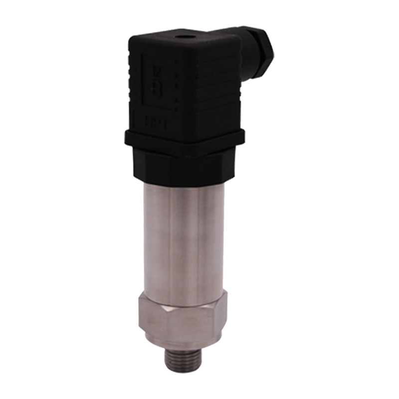
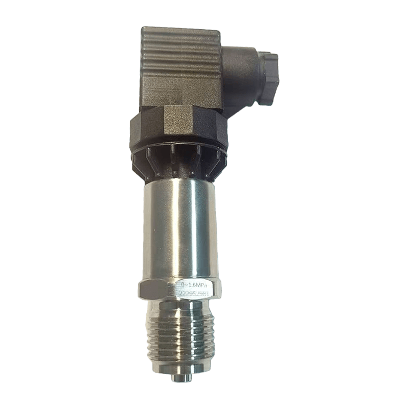
In practice, facility teams rely on a pressure transmitter installed across each critical boundary to continuously report the differential between adjacent rooms. This single measurement point becomes the trigger for HVAC dampers, alarms, and interlocks that keep the facility inside its qualified operating envelope. The consequences of ignoring this discipline are measurable: a pharmaceutical manufacturer that loses positive pressure in a filling suite for even ninety seconds may be required to document, investigate, and in some cases discard the batch in process.
Field note: A contract manufacturer running six ISO 7 suites found that 70 percent of unplanned pressure excursions traced back to door interlock failures rather than HVAC faults, which only became visible once continuous differential logging replaced spot checks with a handheld gauge.
Why Spot Checks Are Not Enough
Many facilities that still rely on periodic manual readings assume the gap between checks is harmless, since the room appears to hold its classification during each inspection. The problem is that a pressure excursion caused by a stuck damper, a failed belt on a supply fan, or a propped-open fire door can develop and resolve itself between two scheduled readings, leaving no trace in the paper log while still exposing the process to an uncontrolled period of airflow reversal. Continuous electronic monitoring closes that gap by recording every reading at short, fixed intervals, so the trend line itself becomes the evidence rather than a handful of isolated data points.
Linking Pressure Control to Product Risk
The relationship between pressure stability and product risk is not uniform across every cleanroom application. A terminal packaging area that only needs to limit gross particulate ingress can tolerate brief, well-documented excursions that would be unacceptable in an aseptic filling line where an open vial is exposed to room air for several seconds during the fill cycle. Facility teams that map each room to its actual risk level, rather than applying one blanket alarm threshold across the entire site, tend to spend less time chasing nuisance alarms in low-risk spaces while keeping tighter tolerances where they genuinely matter.
How Differential Pressure Sensors Maintain Directional Airflow
The Cascade Principle
Cleanroom design almost always follows a cascade, where the cleanest room holds the highest pressure and each successive space toward the corridor or outdoors steps down in defined increments, commonly 10 to 15 pascals per stage. Air is pushed from clean to dirty through door gaps, pass-throughs, and deliberate leakage paths, never the reverse. A differential pressure sensor at each boundary confirms the step is holding, and the building automation system adjusts supply or exhaust volume to correct drift before it becomes visible to an operator.
Reading the Cascade Diagram
The diagram below illustrates a typical three-stage cascade used in aseptic processing areas, moving from the core process room outward to the general corridor.
Each boundary in the diagram is monitored independently rather than inferring the anteroom pressure from the process room reading, because a single sensor cannot detect a localized leak at a second doorway or a failing gasket on a pass-through hatch.
Why Small Increments Matter
Ten to fifteen pascals sounds like a narrow band, and it is, which is exactly why the instrumentation choice at each boundary carries so much weight. A general-purpose differential pressure sensor designed for duct static pressure work in the hundreds of pascals will show almost no meaningful movement across a 15 pascal cascade step, effectively blinding the control system to real drift long before it becomes visible on a coarse instrument. Facilities that standardize on a single wide-range sensor across every application, purely to simplify spare parts inventory, often discover this limitation only after an excursion goes undetected for days.
Balancing Airflow Against Air Change Rate
Maintaining the cascade is not simply a matter of pushing more air into the cleaner room. Air change rate, filter loading, and exhaust capacity all interact, and increasing supply volume without a matched increase in exhaust can create turbulence at doorways that actually degrades unidirectional airflow near the work zone even while the bulk differential reading looks correct. Balancing dampers are typically set during commissioning and rechecked whenever filters are replaced, since a newly installed filter with lower resistance can shift the airflow split enough to alter the pressure relationship between rooms that share a common air handling unit.
Pressure Transmitter Selection Criteria for Cleanroom HVAC Systems
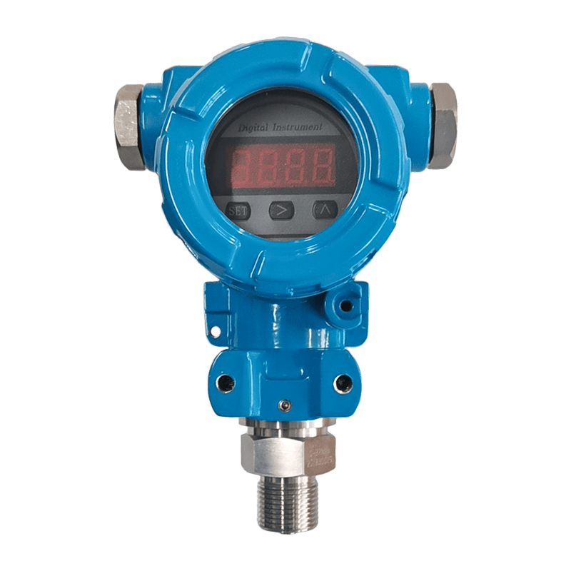
Not every differential pressure sensor is suited to cleanroom duty. The ranges involved are small, often under 50 pascals, and the sensor must resolve changes of 1 pascal or less without drifting over months of continuous operation. Selecting an instrument with too wide a measuring span produces a flat, unresponsive signal that fails to catch gradual filter loading or a slowly opening door seal.
Key Specifications to Compare
- Measuring range matched to the actual cascade step, typically 0 to 25 Pa or 0 to 60 Pa rather than a general-purpose 0 to 2500 Pa unit
- Accuracy stated as a percentage of full scale, with 1 percent or better preferred for validated spaces
- Long-term zero stability, since even a small zero drift over a year can push a room outside its qualified band
- Output signal compatible with the existing building automation system, commonly 4 to 20 mA or 0 to 10 V
- Housing rating suited to washdown or fumigation cycles if the transmitter sits inside the classified space itself
Installation Considerations
Tubing length and routing matter more in cleanroom applications than in general HVAC work. Long capillary runs introduce lag and can trap condensate, which distorts the reading during humid seasons. Wall-mounted units positioned outside the classified envelope, with short reference tubing passing through a sealed wall fitting, tend to hold calibration longer and simplify maintenance access without breaching the room itself.
Signal Stability Over Temperature Swings
Cleanroom mechanical rooms and interstitial spaces where transmitters are often mounted can swing widely in temperature across a day, particularly in facilities without dedicated conditioning for the equipment corridor. A sensor with a poorly compensated temperature coefficient will appear to drift even when the actual room pressure has not changed, which technicians sometimes misdiagnose as an HVAC control problem rather than an instrumentation limitation. Reviewing the published temperature coefficient, not just the room-temperature accuracy figure, avoids this confusion during specification.
Redundancy for Critical Boundaries
For the single highest-risk boundary in a facility, such as the entry to a filling suite, some designs add a second, independently wired sensor purely as a cross-check against the primary control instrument. The two readings do not need to match exactly, but a persistent divergence between them is a reliable early warning that one sensor has drifted out of calibration before either reading crosses an alarm threshold on its own. This approach adds cost, so it is typically reserved for the one or two boundaries where an undetected excursion carries the greatest consequence.
| Application Zone | Typical Range | Recommended Accuracy |
|---|---|---|
| ISO 5 to ISO 7 boundary | 0 to 25 Pa | 1 percent of full scale |
| ISO 7 to ISO 8 boundary | 0 to 60 Pa | 1 to 2 percent of full scale |
| Negative pressure isolation room | 0 to 50 Pa negative | 1 percent of full scale |
| General HVAC duct static | 0 to 500 Pa | 2 percent of full scale |
Level Transmitter Applications in Pharmaceutical Utility Systems
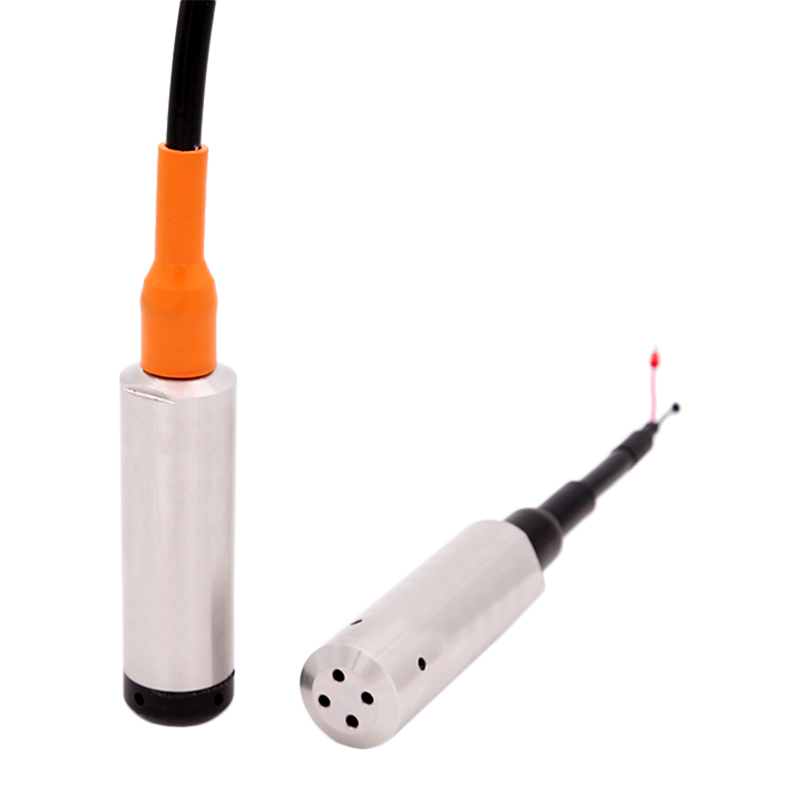
Cleanroom operations depend on more than airflow. Water for injection tanks, clean steam generators, and humidification reservoirs all support the environmental conditions inside the room, and each of them relies on continuous level measurement to avoid dry-running pumps, overflow events, or interrupted humidity control. A level transmitter mounted on these utility vessels feeds the same building automation platform that manages room pressure, allowing operators to correlate a humidity excursion with a falling reservoir level rather than troubleshooting the air handler in isolation.
Where Level Monitoring Intersects with Cleanroom Stability
Steam humidifiers used to hold cleanroom relative humidity within a narrow band, often 45 to 55 percent, draw from a feed tank that must stay within a defined level window. If the tank runs low, humidity output becomes erratic, and static charge buildup on surfaces increases particle adhesion risk. Continuous level feedback lets the control system throttle humidifier demand or trigger a refill alarm before the room drifts out of specification.
Selection Notes for Utility Tank Applications
- Non-contact ultrasonic or radar types avoid fouling in tanks holding treated water or condensate
- Hygienic process connections reduce dead legs where bacteria can colonize in pharmaceutical water systems
- Output should integrate with the same protocol used by the pressure monitoring network to simplify wiring and reduce the number of distinct communication gateways
Coordinating Alarms Across Utility and Room Systems
Treating the level monitoring network and the pressure monitoring network as separate systems, each with its own alarm history and its own maintenance team, makes root cause analysis slower than it needs to be. A humidity excursion investigated in isolation from the utility tank trend can take hours to resolve, while the same event reviewed alongside a falling reservoir level on a shared timeline often points directly to the cause within minutes. Facilities consolidating both data streams into one supervisory dashboard consistently report shorter investigation times for environmental deviations.
Practical Tank Sizing and Refill Strategy
Reservoir sizing also affects how much warning a level transmitter can realistically provide. A tank sized only for a few hours of demand gives operators very little time to respond to a low-level alarm, particularly on a night shift with reduced staffing, while an oversized tank introduces its own risk of water sitting stagnant for extended periods. Facilities that model expected demand against realistic response times, rather than defaulting to whatever tank size fits the available floor space, tend to strike a better balance between alarm lead time and water quality risk.
Negative Pressure Isolation Room Requirements and Monitoring Practices
Negative pressure isolation rooms invert the usual cleanroom logic. Instead of protecting the room from the corridor, the goal is protecting the corridor and adjacent staff from whatever is inside the room, whether that is an infectious patient in a hospital setting or a hazardous compound handled in a containment laboratory. Air must always flow inward, and the differential is typically held between 2.5 and 15 pascals negative relative to the corridor, depending on the applicable design guideline.
Monitoring Practices That Matter Most
| Practice | Purpose |
|---|---|
| Continuous digital display at the room entry | Gives staff an immediate visual check before entering or leaving |
| Local audible alarm on loss of negative pressure | Alerts occupants without requiring a central control room to notice first |
| Data logging at short intervals | Supports incident investigation and regulatory reporting after any excursion |
| Independent sensor per anteroom stage | Prevents a single failed door seal from masking a second leak path |
One detail frequently overlooked during design is door swing direction and closer speed. A door that closes slowly allows a larger volume of air exchange each time it opens, which can momentarily overwhelm the exhaust capacity and produce a false alarm even though the room recovers within seconds. Facilities that pair mechanical closer tuning with a slight alarm delay, rather than an instantaneous trip, tend to see far fewer nuisance alerts without compromising actual containment performance.
Cleanroom Validation and Continuous Monitoring System Design
From Commissioning to Ongoing Qualification
Cleanroom validation typically moves through installation qualification, operational qualification, and performance qualification stages, and pressure differential data is required at each one. During performance qualification, the differential must be demonstrated stable across worst-case conditions, including doors cycling, HVAC systems at minimum outside air, and the maximum expected occupancy load.
Building the Monitoring Architecture
A well-designed monitoring architecture separates three layers: field sensors reporting raw differential and level data, a local controller performing the alarm logic and setpoint comparison, and a supervisory system that logs history, generates trend reports, and manages user access for audit purposes. Keeping these layers distinct makes it possible to replace a single sensor without disrupting the historical trend record tied to that monitoring point.
- Define the pressure cascade map before selecting hardware, including every boundary that requires independent monitoring
- Specify sensor range and accuracy per boundary rather than applying one generic specification across the facility
- Route wiring and reference tubing to avoid thermal gradients that can bias low-range pressure readings
- Configure alarm delays that reflect realistic door-opening events rather than triggering on every transient
- Establish a recurring calibration schedule tied to the criticality of each monitored zone
Airflow monitoring is often paired with the pressure network at this stage, since differential pressure alone cannot confirm that air change rates remain within the qualified range if a filter becomes partially blocked. Facilities that track both differential pressure and supply air velocity catch filter loading trends weeks before the pressure reading alone would flag a problem.
Sensor Calibration and Maintenance Best Practices
Calibration frequency for cleanroom pressure and level instruments is usually driven by criticality rather than a single blanket interval. High-risk aseptic boundaries often justify a six-month cycle, while general HVAC monitoring points in a support area may run on an annual schedule.
| Instrument Class | Typical Calibration Interval | Key Check |
|---|---|---|
| Critical boundary pressure sensor | 6 months | Zero and span against a certified reference gauge |
| Support area pressure sensor | 12 months | Zero verification and visual tubing inspection |
| Utility tank level transmitter | 12 months | Span check against a manual dip reading |
Common Failure Modes
- Blocked or kinked reference tubing producing a falsely stable reading that no longer tracks actual room conditions
- Condensate accumulation in low-range pressure sensors during high-humidity seasons
- Sensor drift caused by repeated exposure to vibration near air handling units
- Firmware or communication faults that freeze the last reported value instead of flagging a fault condition
A documented calibration history also protects the facility during regulatory inspection, since assessors typically ask for evidence that instrument accuracy has been verified across the full life of the validated space, not just at initial commissioning.
Frequently Asked Questions
Q1: What differential pressure range is typical between an ISO 7 cleanroom and its anteroom?
Most designs target 10 to 15 pascals between an ISO 7 space and an adjoining anteroom, though the exact figure depends on door size, air change rate, and the specific guideline the facility follows.
Q2: How often should a pressure differential sensor be recalibrated in a validated cleanroom?
Critical boundaries are commonly checked every six months, while lower-risk support areas can often be verified on an annual cycle, with the interval justified in the facility validation plan.
Q3: Can a single sensor monitor pressure across multiple room boundaries?
No. Each boundary should have its own dedicated sensor, since a shared or averaged reading cannot reveal a localized leak at a secondary doorway or hatch.
Q4: Why does level monitoring matter for cleanroom humidity control?
Humidification and clean steam systems draw from feed tanks that must stay within a defined level window, and continuous level feedback prevents the erratic humidity output that occurs when a reservoir runs low.
Q5: What causes false pressure alarms in negative pressure isolation rooms?
Slow-closing doors and undersized exhaust response during door-opening events are common causes, and tuning door closer speed alongside a short alarm delay usually reduces nuisance alerts without weakening containment.