

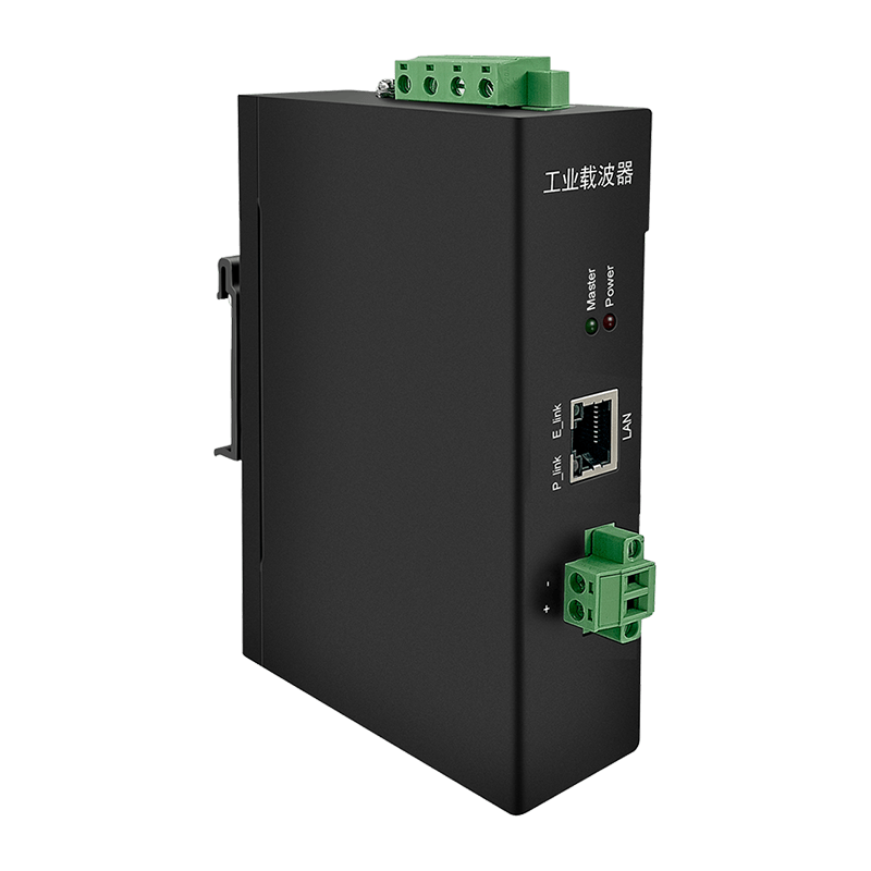
The Evolution of Industrial Power Line Communication
Modern industrial automation demands robust, high-speed data transmission across increasingly complex environments. Traditional networking infrastructures often require dedicated communication cabling, which increases installation costs and limits deployment flexibility. To overcome these constraints, power line communication plc technologies have emerged as a viable alternative, utilizing existing electrical wiring to transmit both electrical power and high-frequency data signals simultaneously.
Among these technologies, High-Definition Power Line Communication represents a major advancement, operating across broader frequency bands to achieve multi-megabit data rates. However, industrial electrical grids are inherently harsh environments characterized by significant electromagnetic interference, transient voltage spikes, and unpredictable impedance fluctuations. Without proper signal conditioning, the data packets transmitted via these networks can suffer from severe degradation, leading to packet loss, increased latency, and complete communication timeouts.
To establish a stable data link, industrial networks rely on specialized hardware solutions designed to separate the high-frequency communication signals from the low-frequency electrical power delivery. Implementing an effective signal isolation strategy is not merely an performance enhancement; it is a fundamental requirement for operational continuity in automated manufacturing, smart grid monitoring, and large-scale industrial IoT deployments.
Understanding Electromagnetic Interference in Industrial Power Grids
Industrial facilities house a dense concentration of heavy machinery, switching power supplies, and automated motor drives. These devices introduce substantial electrical noise into the local power distribution network. This noise manifests in two primary forms: differential mode noise, which flows between the live and neutral conductors, and common mode noise, which flows between the current-carrying conductors and the protective earth ground.
Variable frequency drives and switched-mode power supplies generate high-frequency voltage fluctuations during standard operation, creating continuous broad-spectrum interference across the network.
The connection of diverse industrial loads causes constant fluctuations in line impedance. This mismatch reflects communication signals back toward the source, attenuating the primary data wave.
Parallel routing of high-power cables and communication lines allows electromagnetic fields to induce unwanted noise voltages directly into adjacent data paths, degrading the signal-to-noise ratio.
Because high-definition communication protocols utilize frequency spectrums ranging from several hundred kilohertz up to tens of megahertz, standard electrical noise directly overlaps with the data transmission band. Without a dedicated HD-PLC Power Line Filter, the raw noise levels easily overwhelm the transceiver front-end, making accurate signal demodulation impossible.
The Role of Advanced Band-Pass Filter Solutions
Mitigating noise within a high-speed communication network requires a targeted approach to frequency selection. High-performance networks utilize PLC band-pass filter solutions to isolate the exact frequency spectrum allocated for data transmission while aggressively suppressing frequencies above and below this target window. This dual-action attenuation protects the integrity of the data packets from both low-frequency grid harmonics and high-frequency radio frequency interference.
An effective filter architecture must handle high AC or DC currents without entering magnetic saturation. When a filter inductor saturates due to heavy electrical loads, its effective inductance drops precipitously, rendering the filter incapable of suppressing noise. Therefore, industrial-grade components utilize specialized nanocrystalline or advanced ferrite core materials with high saturation flux densities to guarantee consistent attenuation performance across all operational load conditions.
Performance Specifications and Attenuation Characteristics
Selecting the correct filtering components requires a quantitative analysis of attenuation performance across key operational frequencies. A professional power line noise suppressor must provide precise impedance characteristics to prevent signal leakage into adjacent non-communicating electrical branches while maintaining minimal insertion loss within the primary data channel.
The following performance distribution details the attenuation parameters required to secure comprehensive industrial communication signal protection across standard manufacturing distribution panels:
| Frequency Range | Target Component | Minimum Attenuation | Operational Impact |
|---|---|---|---|
| 9 kHz to 150 kHz | Low-Frequency Harmonics | 35 dB | Suppresses motor drive fundamental switching frequencies |
| 150 kHz to 2 MHz | Narrowband Interference | 50 dB | Eliminates primary switch-mode supply noise transients |
| 2 MHz to 30 MHz | HD-PLC Data Carrier Band | Less than 2 dB (Insertion Loss) | Preserves localized communication signal amplitude |
| 30 MHz to 100 MHz | High-Frequency Radiated RFI | 40 dB | Blocks ambient radio frequency coupling from nearby cabling |
By enforcing a high attenuation profile outside the communication band, an Industrial Grade Power Line Isolator Filter prevents external electrical noise from corrupting the high-frequency carrier waves. Simultaneously, it prevents the communication signals themselves from radiating outward and interfering with other sensitive laboratory or telemetry equipment sharing the same power infrastructure.
Strategic Deployment and Topology Mapping
The physical location of filtering and isolation hardware within an electrical topology directly determines the ultimate stability of the communication network. Filters must be positioned at critical intersection points where noise-generating equipment connects to the shared distribution line. This method isolates noise sources at the point of origin, preventing electromagnetic interference from propagating throughout the facility infrastructure.
When designing an industrial installation layout, field engineers should categorize network nodes into distinct zones based on power consumption and noise generation potential. High-power loads, such as heavy-duty pumps, welding stations, and thermal furnaces, require dedicated isolation units at their primary distribution blocks. Concurrently, sensitive data collection points require localized EMI filter for PLC integration to establish a shielded localized signal environment.
Operational Rule: Never route unshielded power cables parallel to isolated communication lines over long physical distances. Electrostatic and electromagnetic coupling can bypass standard inline filtering mechanisms, reintroducing broadband noise into clean sections of the power distribution grid.
Physical Product Integration and Installation Metrics
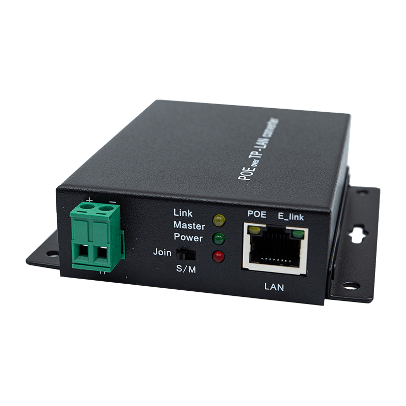
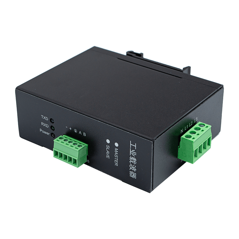
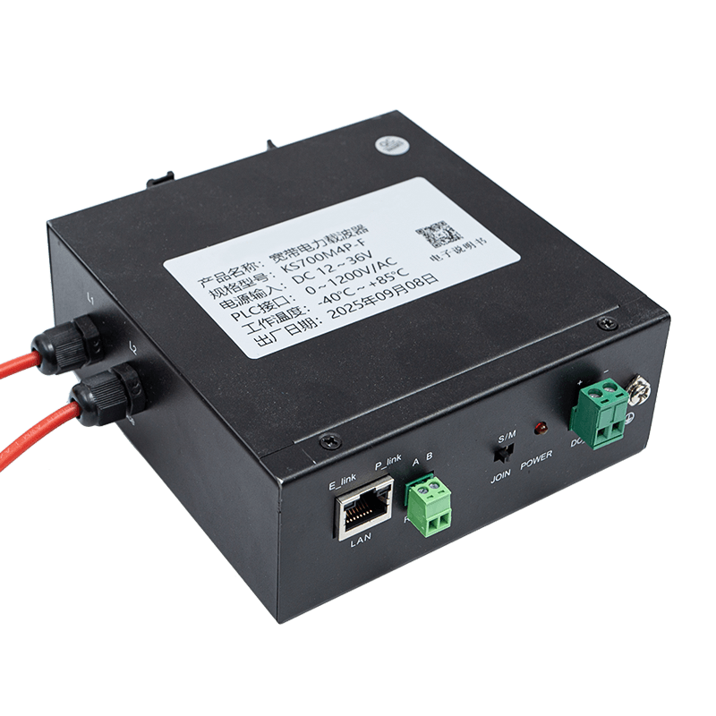
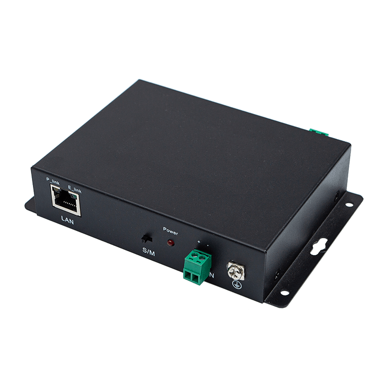
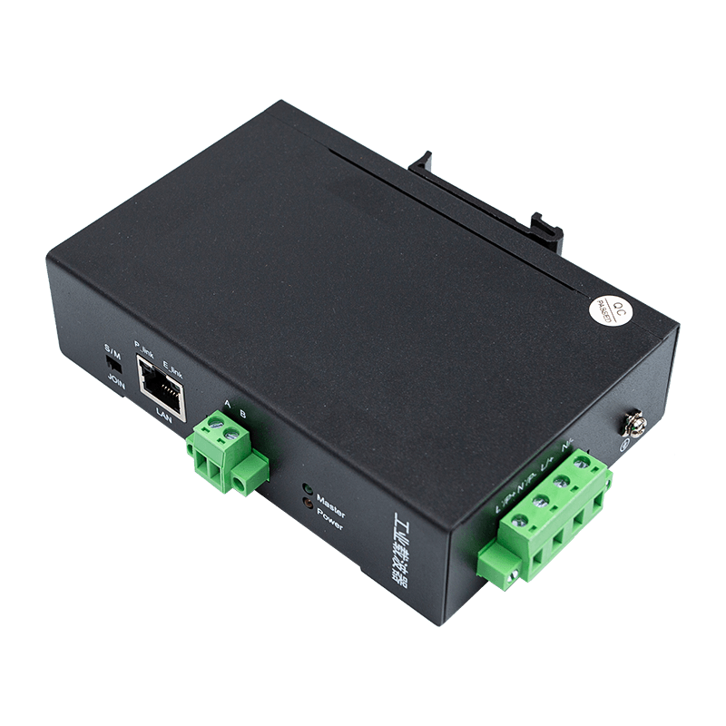
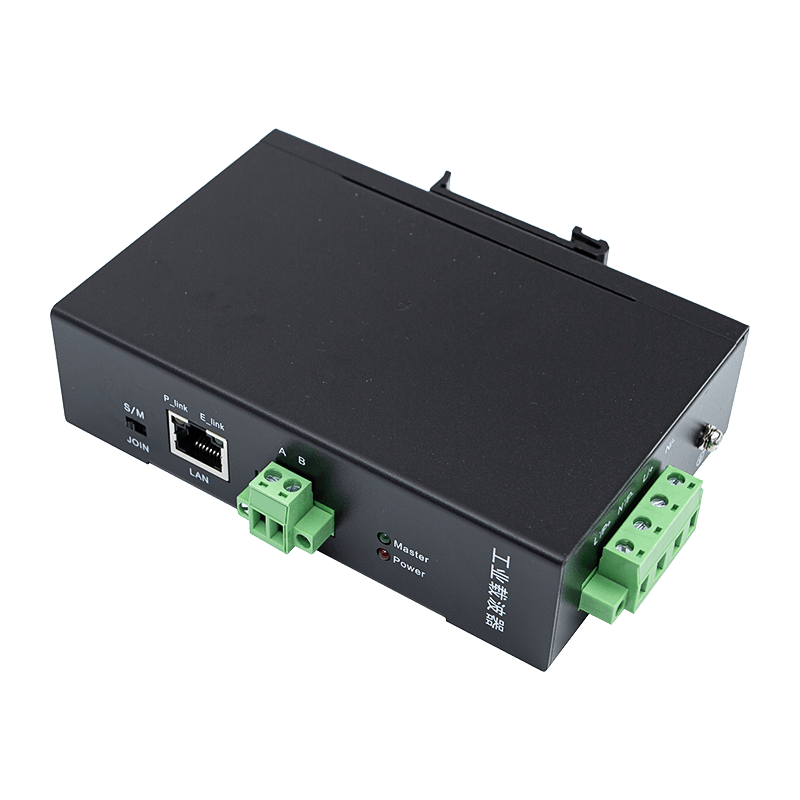
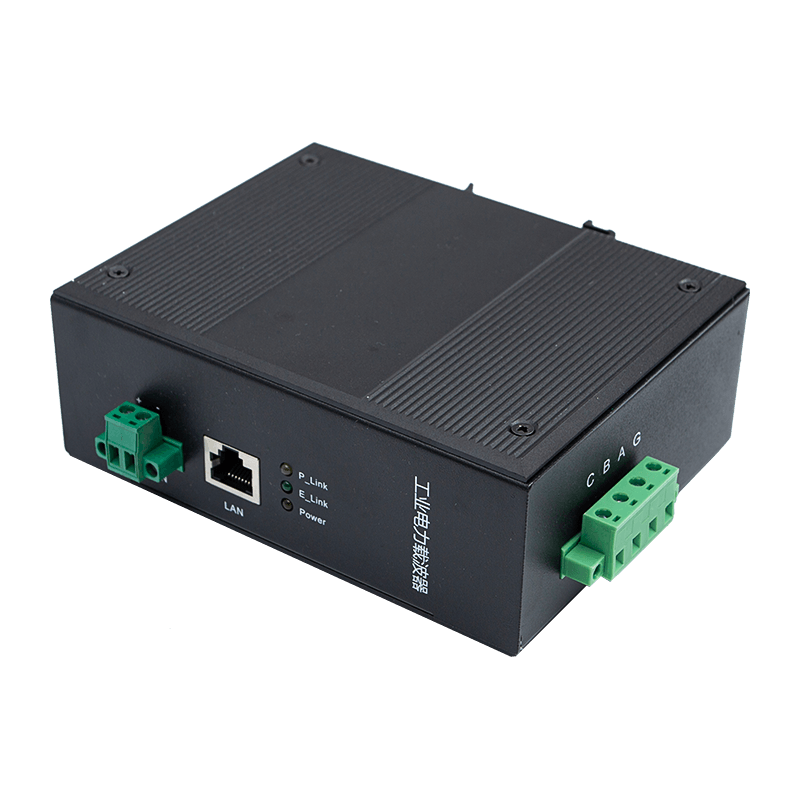
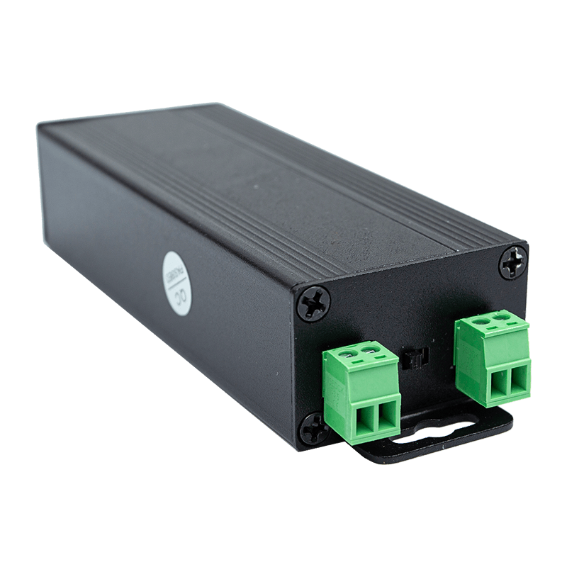
To ensure long-term survivability in demanding environments, filtering hardware must match the physical and thermal constraints of standard industrial control enclosures. Heavy-duty DIN-rail mount housings facilitate rapid integration within existing electrical cabinets, ensuring dense component configurations remain organized and maintainable over decades of service.
To view an example of industrial housing designs and configuration interfaces, refer to the verified installation schematic provided below:
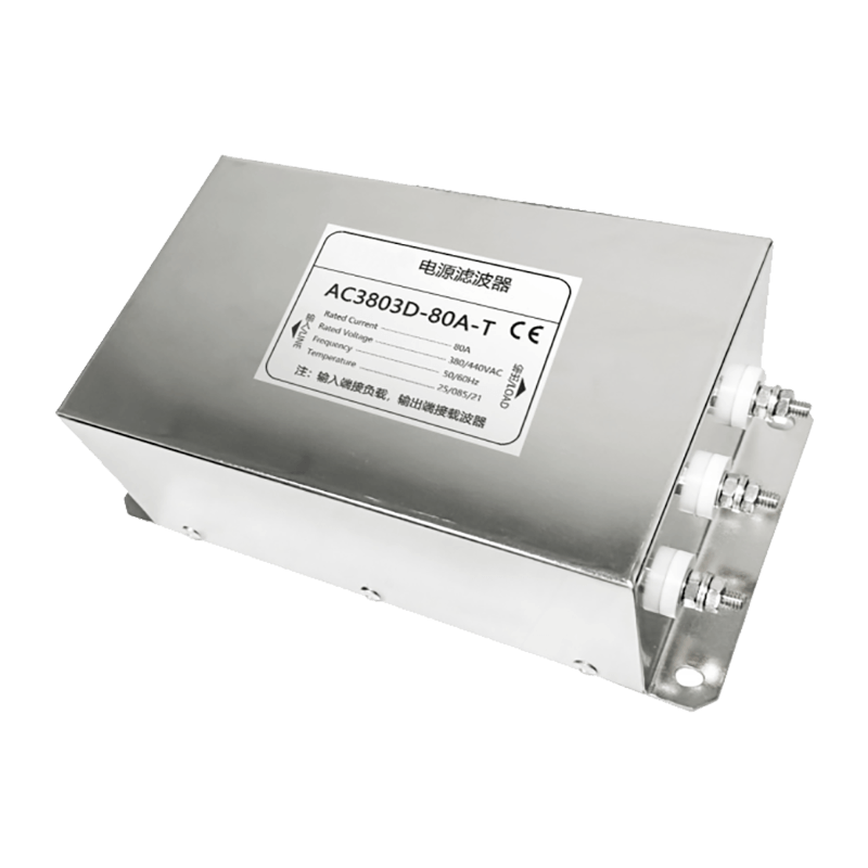
During physical installation, lead lengths between the filter terminal and the primary distribution block must be kept as short as possible. Long wire leads possess inherent stray inductance, which creates a high-impedance path at high frequencies. This stray inductance can severely degrade the filter's high-frequency performance, effectively allowing high-frequency noise components to pass around the isolation network via parasitic capacitive paths.
Empirical Evaluation of Noise Isolation Systems
The practical necessity of robust power line isolation is best demonstrated through real-world deployment data gathered from automated assembly environments. In an automated automotive assembly facility, a localized communication network tracking component logistics experienced severe data degradation, with packet drop rates peaking at twenty-four percent during peak operational shifts. This data loss forced the control software to trigger repeated retransmissions, elevating network latency to levels that disrupted real-time synchronization.
Engineers performed a comprehensive spectrum analysis of the power lines, revealing intense broadband noise concentrated between 5 MHz and 15 MHz, originating from a bank of adjacent multi-axis robotic welding units. The noise levels exceeded the maximum input threshold of the standard communication transceivers, causing data packet corruption.
To resolve this issue, the technical team implemented a multi-tiered isolation strategy: individual high-attenuation isolation filters were installed on the power feeds of each robotic welding controller, and dedicated band-pass filter solutions were deployed directly upstream of the communication nodes. The post-implementation monitoring phase demonstrated a significant improvement in network performance metrics, which are detailed below:
- Packet Error Rate Reduction: The overall packet error rate dropped from the initial twenty-four percent to less than 0.05 percent across continuous seventy-two-hour testing cycles.
- Latency Stabilization: Mean data latency was restored to a predictable three milliseconds, completely eliminating the transmission spikes that previously caused automated system stops.
- Signal-to-Noise Ratio Improvement: The clear signal margin across the primary communication frequencies increased by an average of twenty-eight decibels, ensuring reliable long-term data processing.
Frequently Asked Questions Regarding Signal Isolation
Q1: How does an industrial power line filter differ from a standard commercial surge protector?
Industrial power line filters are precision-engineered to provide continuous, bidirectional attenuation of high-frequency electromagnetic interference across specific frequency bands while handling high operational currents. Standard commercial surge protectors are designed primarily to clamp brief, high-voltage transient spikes using metal oxide varistors, offering minimal to no attenuation for continuous high-frequency communication noise.
Q2: Can a single filter protect an entire industrial automated network?
No, a single filter cannot protect an entire network distributed across a large physical area. Industrial facilities contain multiple distributed noise sources; therefore, filters must be strategically deployed at individual high-noise generation points and sensitive receiver nodes to prevent noise from propagating through shared wiring paths.
Q3: What causes an isolation filter to experience thermal overheating during standard operation?
Thermal overheating is typically caused by magnetic core saturation or excessive continuous current draws that exceed the filter's rated capacity. Selecting a filter with high-saturation core materials and appropriate current ratings ensures cool, stable operation under full industrial load configurations.
Q4: Does the installation of a power line filter attenuate the actual communication signal?
A properly specified band-pass filter will exhibit extremely low insertion loss—typically less than two decibels—within the specific frequency band allocated for data transmission. This ensures that while unwanted noise is heavily suppressed, the primary communication signals pass through with minimal attenuation.
Q5: How do field technicians verify if an installed filter is operating effectively?
Technicians use a high-frequency spectrum analyzer or a dedicated power line noise meter to measure the noise amplitude upstream and downstream of the filter. A properly functioning filter will show a distinct drop in noise floor amplitude across the targeted suppression frequencies according to its rated decibel attenuation specification.