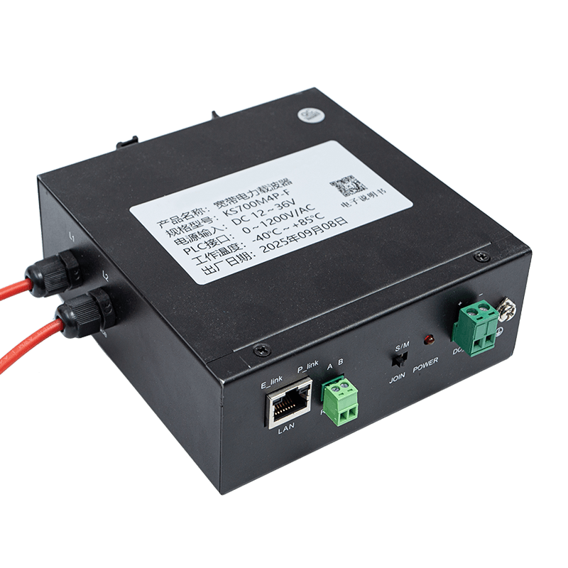


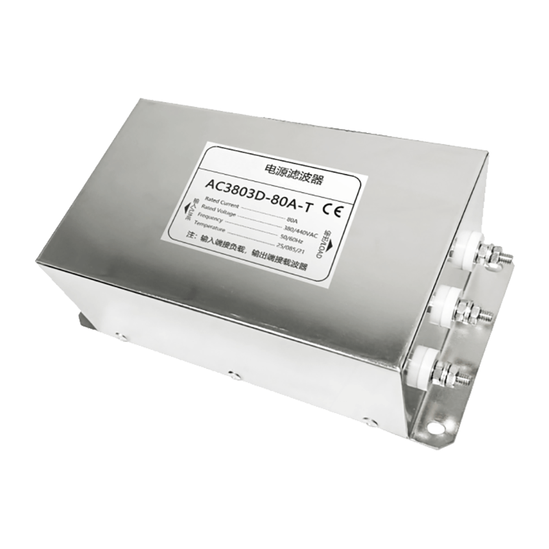
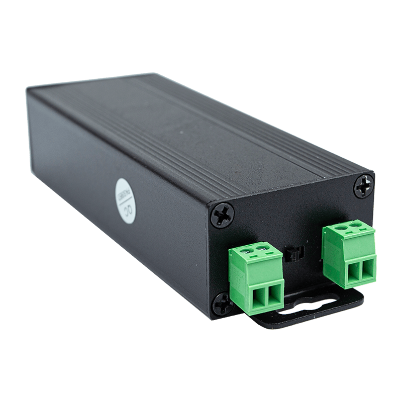
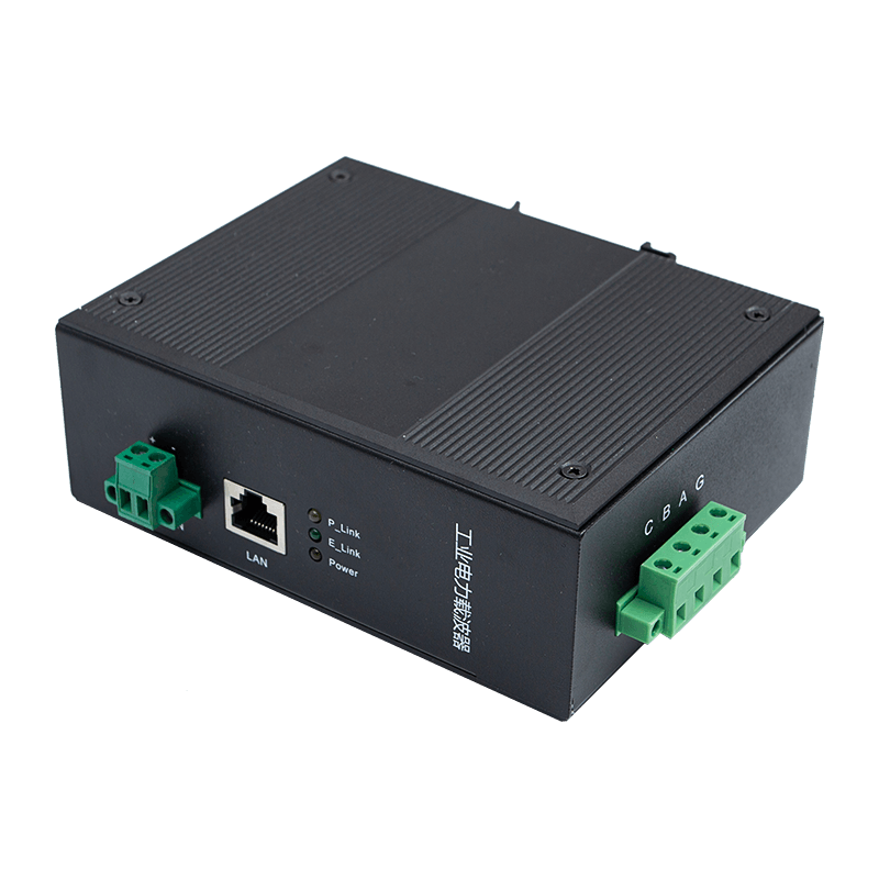
Power line communication (PLC) technology transforms existing electrical wiring into a data transmission medium, enabling High-speed Power Line Communication without laying new cable infrastructure. While this approach offers significant cost advantages, the electrical grid was never designed with data integrity in mind. The result is a communication channel subjected to a relentless barrage of interference, from switching transients and motor harmonics to cross-network crosstalk and ambient electromagnetic radiation.
Noise in a broadband PLC system is not a single phenomenon. It is a composite of multiple interference types, each with distinct frequency characteristics, sources, and mitigation strategies. Understanding this complexity is the first step toward deploying a high-performance PLC network. This guide provides a structured, technically grounded approach to identifying, measuring, and suppressing the primary noise sources that degrade broadband PLC performance.
Understanding Noise Categories in Power Line Environments
Before selecting any mitigation technique, engineers must characterize the noise environment. Broadband PLC typically operates in the 1 MHz to 100 MHz frequency range, where interference mechanisms differ substantially from those encountered in audio-frequency or narrowband systems. Four primary noise categories dominate this spectrum.
Colored Background Noise
This low-level, broadband noise arises from the superposition of numerous low-power interference sources. Its power spectral density decreases with rising frequency, which means the 1–10 MHz band is more severely affected than the 50–100 MHz range. Typical sources include household appliances in standby mode, power supply switching artifacts from consumer electronics, and leakage currents through parasitic capacitances in wiring. Background noise floors in residential environments commonly range from -130 dBm/Hz to -110 dBm/Hz.
Narrowband Interference
Narrowband interference appears as discrete spectral lines superimposed on the noise floor. Amateur radio transmissions, shortwave broadcast bands, and switching power supplies with stable oscillators are common culprits. These tones can be 40–60 dB above the background noise floor, effectively rendering specific PLC subcarriers unusable. Adaptive bit-loading algorithms can mitigate narrowband interference by zeroing out affected subcarriers, but persistent strong tones reduce overall system throughput significantly.
Periodic Impulsive Noise Synchronous with the Mains
This interference is generated by loads that switch in synchrony with the 50 Hz or 60 Hz power cycle, such as phase-controlled dimmers and thyristor motor drives. It appears at twice the mains frequency and its harmonics, creating a predictable but highly disruptive burst pattern. Burst durations typically range from 10 microseconds to several hundred microseconds, with peak amplitudes that can exceed 50 dBmV in residential wiring.
Aperiodic Impulsive Noise
Aperiodic impulses are the most destructive noise category. They occur randomly, are unpredictable, and can have spectral components spanning the entire PLC operating band. Switching transients from large inductive loads, relay contacts, and motor startup events produce peaks that routinely reach 80–100 dBmV, far exceeding the dynamic range of most PLC receivers. A single impulse can corrupt dozens of OFDM symbols simultaneously.
| Noise Type | Frequency Range | Typical Peak Amplitude | Primary Source |
|---|---|---|---|
| Colored Background | 1–100 MHz | -130 to -110 dBm/Hz | Aggregate low-power sources |
| Narrowband Interference | Discrete tones | Up to -60 dBm/Hz | Radio broadcasts, switching PSUs |
| Periodic Impulsive | Harmonics of mains | 30–50 dBmV | Dimmers, thyristor drives |
| Aperiodic Impulsive | Full PLC band | 80–100 dBmV | Motor startups, relay contacts |
Signal Attenuation on Power Lines: What Reduces PLC Range
Signal attenuation on power lines is frequency-dependent and topology-dependent. Unlike coaxial or twisted-pair cable, power line wiring was designed for 50/60 Hz current delivery, not RF propagation. Several physical mechanisms contribute to attenuation.
Resistive and Skin-Effect Losses
At DC, conductor resistance is the primary loss mechanism. As frequency rises into the PLC operating band, the skin effect concentrates current in a progressively thinner layer near the conductor surface, increasing effective resistance. For a 2.5 mm2 copper conductor, AC resistance at 30 MHz is approximately 4–6 times higher than the DC value. Over a 100-meter run, this translates into 10–15 dB of additional attenuation compared to the DC case.
Impedance Mismatches and Reflections
Power line impedance varies dramatically based on the number of connected loads, cable type, junction boxes, and installation geometry. Characteristic impedance typically ranges from 2 ohms to 200 ohms across the PLC band, with rapid variations as loads are connected or disconnected. Each impedance discontinuity produces a partial reflection, causing destructive interference at certain frequencies and creating frequency-selective fading. This manifests as sharp dips in the channel transfer function, sometimes exceeding 20 dB at specific frequencies.
Load-Induced Attenuation
Connected appliances act as shunt impedances that absorb PLC signal power. Switching mode power supplies present very low impedance at high frequencies due to their input capacitors, often 0.1–10 ohms across the PLC band. A cluster of computers or televisions connected to the same circuit can attenuate PLC signals by 20–40 dB compared to an unloaded line. This is one of the primary reasons why High-speed Power Line Communication requires dedicated line conditioning in dense load environments.
PLC Line Filter Design and Selection
A PLC line filter serves a dual purpose: it prevents high-frequency noise on the power line from entering the PLC receiver, and it prevents PLC signals from leaking onto circuits where they do not belong. Proper filter design is arguably the single most impactful intervention available to a PLC system designer.
Low-Pass Filter at the Service Entry Point
Installing a low-pass filter at the point where utility power enters a building confines noise from external sources and prevents the internal PLC network from radiating energy back into the grid. A well-designed entry-point filter should provide at least 40 dB of attenuation above 1 MHz while maintaining negligible impedance at 50/60 Hz. Ferrite-core common-mode chokes combined with ceramic capacitors are the preferred topology, as they address both differential-mode and common-mode interference simultaneously.
Appliance-Level High-Frequency Noise Suppression
Individual noise-generating appliances should be filtered at their power entry points. Switching mode power supplies are the most common culprits. A well-placed X-class capacitor across the line, combined with a Y-class capacitor from each line to earth and a common-mode choke, can reduce conducted emissions from a switching supply by 20–40 dB. This is sometimes referred to as an equipment-level EMI filter and is particularly effective when dealing with variable-speed motor drives or inverter-based systems.
Band-Stop Filters for Narrowband Interference
When a persistent narrowband interferer cannot be eliminated at its source, a notch filter tuned to the offending frequency can protect specific PLC subcarriers. Notch filters in the PLC context typically achieve 20–30 dB rejection in a bandwidth of a few hundred kilohertz. The trade-off is that the filtered frequencies become unavailable for data transmission, reducing spectral efficiency in that band segment.
Filter Placement Strategy
- Service entry: Broadband low-pass filter preventing external noise ingress and signal egress, rated for full service current.
- Sub-panel boundaries: Filters isolating segments of the internal network to prevent noise from one circuit from contaminating others.
- Load-side of noisy appliances: Equipment-level filters on switching supplies, motor drives, and dimmers.
- Near PLC modems: High-performance bandpass filters centered on the operating band to maximize the signal-to-noise ratio at the modem input.
Electromagnetic Interference Mitigation Strategies
Electromagnetic interference in PLC systems has two faces: conducted interference that travels along the power line conductor, and radiated interference that couples into the power line from external sources or from nearby wiring. Both mechanisms must be addressed systematically.
Grounding and Bonding Practices
A well-designed grounding system is the foundation of EMI control. High-frequency ground loops introduce common-mode noise that is particularly damaging to PLC receivers because it adds directly to the received signal. All grounding conductors in the PLC installation zone should converge at a single star point rather than forming loops. The ground impedance at PLC frequencies must be minimized; at 10 MHz, even a short ground lead with 1 microhenry of inductance presents 63 ohms of impedance, which is comparable to the power line characteristic impedance itself.
Shielding of Sensitive Equipment
PLC couplers, modems, and signal injection circuits should be housed in shielded enclosures with proper aperture control. Shielding effectiveness of 40–60 dB is achievable with properly constructed metal enclosures. Every aperture in the shield, whether for connectors, ventilation, or displays, reduces effectiveness at frequencies where the aperture dimension approaches a significant fraction of a wavelength. At 30 MHz, a one-centimeter aperture is approximately 1/1000 of a wavelength, which limits shielding degradation. At 100 MHz, the same aperture represents 1/300 of a wavelength, and shielding effectiveness begins to suffer.
Cable Routing and Separation
Power cables carrying high-frequency PLC signals should be routed away from signal cables and control wiring. A separation of at least 150 mm is recommended for parallel runs. Where crossing is unavoidable, cables should cross at 90-degree angles to minimize inductive coupling. In industrial environments with large motor drives, separation distances of 300–500 mm may be necessary to achieve acceptable noise levels.
Phase Coupler Design and Network Topology Optimization
In three-phase installations and in buildings where circuits span multiple phases, PLC signals transmitted on one phase may not reach devices connected to another phase. Phase coupling is the technique used to bridge this gap and extend the reach of a PLC network across the full electrical installation.
How Phase Couplers Work
A phase coupler is a passive network, typically comprising capacitors or a transformer, that creates a low-impedance path for PLC signals between phases while blocking the 50/60 Hz mains voltage. Capacitive phase couplers use the reactance of series capacitors to couple the high-frequency PLC signal across phases. At 10 MHz, a 10 nF capacitor presents approximately 1.6 ohms of reactance, providing an efficient coupling path with minimal signal loss. Inductive phase couplers use a broadband transformer wound on a ferrite core, offering better impedance matching and higher coupling efficiency over a wider frequency range.
Insertion Loss and Coupling Efficiency
A well-designed phase coupler should introduce no more than 3–6 dB of insertion loss across the PLC operating band. Poorly designed couplers or couplers with inadequate ferrite core material can introduce 15–20 dB of insertion loss, negating much of the benefit. The coupling transformer must be designed with sufficient primary and secondary inductance to maintain acceptable impedance at the lowest PLC frequency in use, typically around 1–2 MHz.
Placement Recommendations
- At the main distribution panel: Phase couplers at the distribution board provide the broadest network coverage and the simplest installation. They ensure every circuit in the building participates in the PLC network.
- At sub-panels in large installations: For buildings with multiple sub-panels, a coupler at each sub-panel ensures that the local network segment is fully interconnected before signals are passed to the main panel coupler.
- Avoiding noisy coupling points: Never install a phase coupler immediately adjacent to large motor drives or variable-frequency drives. The switching noise from these devices will be efficiently coupled across all phases by the coupler.
Network Segmentation for Noise Control
In environments with particularly high noise levels, deliberate network segmentation using bandpass filters between segments can dramatically improve performance. Each segment is a self-contained PLC network, and a gateway device bridges data between segments. This architecture prevents noise generated in one segment from propagating into others. Industrial PLC deployments often use this three-segment approach: a clean segment for sensitive data collection, a standard segment for general networking, and an isolated segment for circuits adjacent to heavy machinery.
Modulation and Signal Processing Techniques for Noise Resilience
Hardware filtering and physical mitigation are essential but insufficient on their own. Modern broadband PLC systems achieve high throughput despite noisy channels through adaptive signal processing techniques embedded in the modem chipset. Understanding these techniques helps engineers make better system configuration decisions.
OFDM and Adaptive Bit-Loading
Orthogonal frequency-division multiplexing divides the PLC band into hundreds or thousands of narrow subcarriers. Each subcarrier can be independently assigned a modulation order ranging from BPSK through 4096-QAM based on the measured signal-to-noise ratio at that specific frequency. Subcarriers experiencing severe narrowband interference or deep fading are assigned a lower modulation order or disabled entirely. This flexibility means the system extracts maximum capacity from the available channel while maintaining a target error rate. A typical broadband PLC channel might support 1024-QAM on 60% of subcarriers, 256-QAM on 25%, lower orders on 10%, and silence on the remaining 5% due to interference.
Robust Forward Error Correction
Impulsive noise events corrupt bursts of consecutive OFDM symbols. Modern PLC systems employ interleaving combined with powerful forward error correction codes, typically convolutional codes with constraint lengths of 7–9 or turbo codes, to spread the impact of burst errors across many codewords. After de-interleaving at the receiver, the burst becomes a pattern of isolated random errors that the FEC code can correct. With well-designed interleaving depths spanning multiple milliseconds, systems can correct impulse bursts of several hundred microseconds without data loss.
Tone Masking and Dynamic Spectrum Access
Regulatory requirements in many jurisdictions mandate that PLC systems avoid transmitting on specific frequencies allocated to radio services, such as amateur radio bands. Tone masking zeros out the relevant subcarriers entirely, preventing interference to external services. Additionally, dynamic spectrum access allows the PLC system to scan the channel and autonomously identify and avoid frequencies currently occupied by strong narrowband interference. This process typically runs continuously, adapting the tone map every few seconds in environments where interference patterns change frequently.
Hybrid ARQ and Retransmission Protocols
Even with robust FEC, occasional packet loss occurs when impulsive events are particularly severe. Hybrid automatic repeat request combines FEC with selective retransmission. When a packet cannot be corrected by FEC, the receiver requests retransmission of only the corrupted packet rather than the entire transmission. Modern implementations use chase combining or incremental redundancy, where retransmitted packets are combined with the first received copy to improve the probability of successful decoding, effectively using all received copies of the data rather than discarding failed attempts.
Measuring and Diagnosing Noise in PLC Installations
Effective noise mitigation requires accurate measurement. Intuition and assumptions frequently lead to misdiagnosis, wasted filter expenditure, and persistent performance problems. A systematic measurement approach identifies both the dominant noise mechanism and the primary noise source before any mitigation hardware is selected.
Essential Measurement Tools
- Spectrum analyzer with appropriate coupling: A calibrated spectrum analyzer connected to the power line through a coupling adapter and isolation transformer reveals the full noise spectral density. Measurements should be taken with loads connected and disconnected to identify the contribution of individual appliances.
- Oscilloscope with high bandwidth: A 200 MHz or greater bandwidth oscilloscope captures the time-domain characteristics of impulsive noise events, including amplitude, duration, and repetition rate. Triggering on impulsive events allows precise characterization of the worst-case interference.
- PLC channel analyzer: Dedicated PLC test equipment measures channel transfer function, attenuation versus frequency, and achievable data rate under current noise conditions. This provides a direct assessment of system performance headroom.
- Power quality meter: Measures mains voltage distortion, harmonic content, and transient events, which correlate with PLC noise sources and help prioritize mitigation efforts.
Systematic Noise Source Identification
The most effective diagnostic procedure follows a process of elimination. Begin by measuring noise with all loads disconnected from the circuit under test. This establishes the baseline noise floor contributed by the grid and the wiring itself. Reconnect loads one at a time, measuring the noise floor after each addition. Loads that cause a significant increase in the noise floor are primary mitigation targets. In practice, it is common for a single piece of equipment to be responsible for the majority of the PLC noise problem.
Interpreting Measurement Results
A noise floor that decreases by 3–5 dB per octave above the PLC band minimum is consistent with colored background noise. Discrete spectral peaks indicate narrowband interference; their frequency can be cross-referenced with known interference sources such as switching power supply oscillator harmonics or radio broadcast frequencies. A noise floor that exhibits periodicity synchronized to the mains frequency during time-domain capture is the signature of periodic impulsive noise from phase-controlled loads. Random, high-amplitude spikes with no apparent periodicity indicate aperiodic impulsive noise from switching transients.
Installation Best Practices for Noise-Resilient PLC Networks
Noise mitigation is most cost-effective when integrated into the system design from the beginning rather than added retroactively. The following practices, when applied consistently, produce PLC installations that maintain high performance even in electrically challenging environments.
Pre-Installation Site Survey
Before committing to a PLC deployment, a site survey using a handheld spectrum analyzer and coupling adapter assesses the suitability of the existing wiring. Key parameters to measure include the average noise floor across the intended operating band, the presence and amplitude of narrowband interferers, the occurrence rate and amplitude of impulsive noise events, and the signal attenuation between planned modem locations. If attenuation between key locations exceeds 50 dB or the noise floor is within 10 dB of the expected signal level, additional mitigation measures must be planned before deployment.
Dedicated Circuits for PLC Infrastructure
Where possible, PLC modems and the devices they serve should share a dedicated circuit branch that does not supply noisy loads. This significantly reduces in-circuit noise by removing the primary noise generators from the same wiring segment as the PLC equipment. If dedicated circuits are not feasible, installing equipment-level filters on all loads sharing the PLC circuit is the next best option.
Regular Performance Monitoring
PLC channel conditions change as loads are added, removed, or replaced. A performance monitoring system that logs data rates, packet error rates, and retransmission counts over time identifies degradation trends before they become outages. Most professional-grade PLC equipment provides SNMP or API-accessible performance counters that can feed into a network management system. Establishing baseline performance metrics immediately after commissioning makes it straightforward to detect when channel conditions have deteriorated and intervention is required.
| Mitigation Technique | Noise Type Addressed | Typical Improvement | Implementation Complexity |
|---|---|---|---|
| Entry-point low-pass filter | Conducted (grid-sourced) | 20–40 dB reduction | Low |
| Equipment-level EMI filter | Conducted (appliance-sourced) | 20–40 dB reduction | Low |
| Notch filter | Narrowband interference | 20–30 dB at target freq | Medium |
| Phase coupler | Cross-phase signal loss | 10–20 dB gain | Medium |
| Network segmentation | All conducted types | 15–30 dB isolation | High |
| Adaptive bit-loading (OFDM) | Narrowband + fading | 30–50% throughput gain | Software (modem-level) |
| Hybrid ARQ | Aperiodic impulsive | Near-zero packet loss | Software (modem-level) |
Frequently Asked Questions
Q1: What is the most common cause of poor throughput in a broadband PLC installation?
The most common cause is connected loads, particularly switching mode power supplies in computers, televisions, and network equipment. These devices present very low impedance at PLC frequencies, absorbing signal power and simultaneously injecting conducted noise. Installing equipment-level EMI filters on the heaviest offenders, identified through spectrum analysis with loads connected and disconnected sequentially, typically produces the largest single improvement in throughput.
Q2: How do I know if I need a phase coupler in my installation?
You need a phase coupler if devices on different electrical phases cannot communicate reliably, or if measured signal attenuation between locations on different phases exceeds 30–40 dB. In North American split-phase systems and European three-phase systems, phase coupling is almost always required for whole-building PLC coverage. The easiest diagnostic test is to measure the channel attenuation directly between two PLC modems placed on different phases.
Q3: Can I use a standard power strip surge protector as a PLC line filter?
No. Consumer surge protectors use varistors or gas discharge tubes that respond to voltage spikes but provide little or no filtering of the continuous high-frequency noise that degrades PLC performance. Additionally, the capacitors in surge protectors are often optimized for transient clamping rather than high-frequency noise rejection. A dedicated PLC line filter with properly designed ferrite chokes and X-Y capacitors is required for effective noise suppression in the PLC operating band.
Q4: How much signal attenuation is acceptable for a broadband PLC system?
Most broadband PLC systems can maintain reliable high-speed communication when the total channel attenuation remains below 50–60 dB, assuming a typical noise floor. Above 60 dB, throughput degrades significantly and connection reliability may be compromised. Attenuation above 80 dB generally prevents reliable communication without repeaters or additional infrastructure. Channel attenuation should be measured across the full operating band, not just at a single frequency, because the transfer function is typically highly frequency-selective.
Q5: Does the length of power line cable significantly affect PLC performance?
Cable length contributes to attenuation through resistive losses and the skin effect, but it is often less significant than the number and type of loads connected to the cable. A 50-meter run with multiple switching power supplies connected can exhibit higher attenuation than a 200-meter run with only resistive loads. In practice, impedance mismatches at junction boxes and load connection points often dominate the attenuation characteristic of longer runs, producing frequency-selective dips rather than uniform roll-off.
Q6: Is it possible to use PLC alongside other broadband technologies on the same wiring?
Yes, but coordination is required. If other technologies such as DSL operate on the same physical conductor, their frequency bands must not overlap with the PLC operating band. Properly specified band-separation filters ensure that each technology occupies its designated spectrum without interfering with the others. In practice, most residential broadband PLC deployments on the 2–86 MHz band do not conflict with standard DSL services, which operate below 17 MHz in the case of VDSL2 or below 35 MHz for G.fast, provided that appropriate filters are installed at the DSL modem and at the PLC signal injection point.
Q7: How does outdoor or underground wiring affect PLC noise levels?
Underground and outdoor cables generally exhibit lower noise levels than indoor wiring because they are not co-routed with high-frequency interference sources. However, they introduce different challenges: moisture ingress at termination points can alter impedance and increase attenuation, and long underground runs can act as efficient antennas for external radio-frequency interference in the 1–30 MHz range. Shielded underground cable with continuous earth bonding provides significantly better PLC performance than unshielded varieties in outdoor applications.