

How Thermal Mass Flow Measurement Actually Works
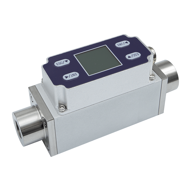
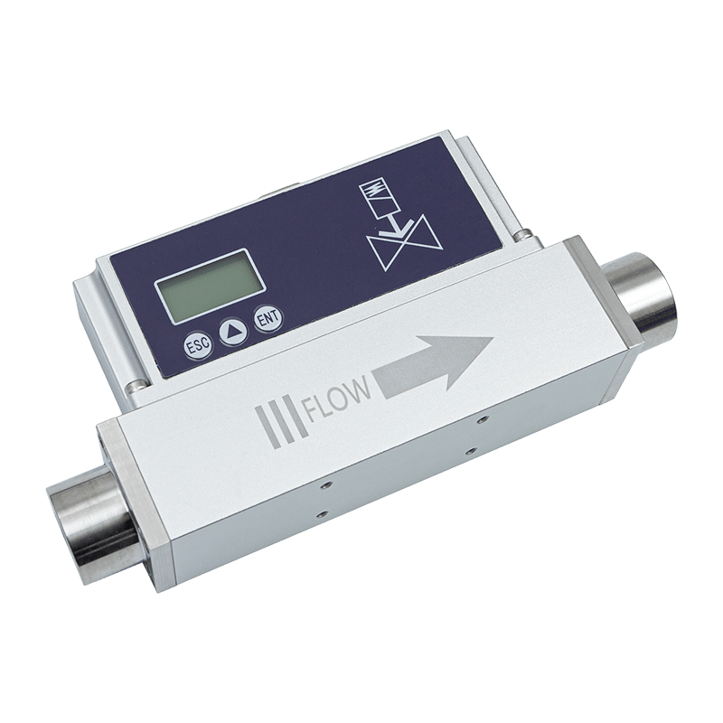
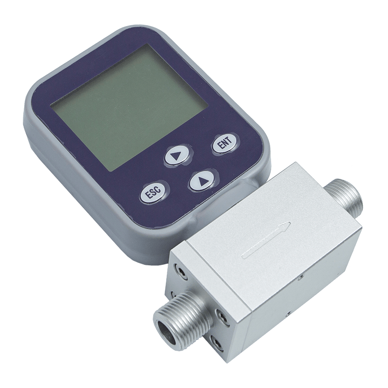
A thermal gas mass flow meter measures gas by sensing how much heat is carried away as gas molecules pass across a heated element. Unlike differential pressure or vortex devices, it reports mass flow directly, without separate temperature and pressure compensation in most low-pressure air and gas services. This makes it a practical choice for plant teams that want a single reading they can trust without running secondary calculations.
Inside the sensor housing, two elements sit in the gas stream. One measures the process gas temperature. The other is heated slightly above that reference point and held there by a control circuit. As gas velocity increases, more heat is pulled away from the heated element, and the circuit has to supply more power to keep it at the set temperature offset. That power draw correlates with mass flow, and the electronics convert it into a flow signal.
Figure 1: Signal Path Inside a Thermal Mass Flow Sensor
Because the response tracks molecular mass movement rather than volumetric velocity alone, the reading naturally accounts for gas density changes caused by pressure or temperature swings within the sensor calibration range. That property is a major reason plants select this technology for compressed air, nitrogen, and process gas monitoring where conditions rarely stay perfectly constant.
This is also why the instrument tends to simplify a control panel rather than complicate it. A volumetric device paired with separate pressure and temperature transmitters needs a controller or flow computer to combine three signals into one usable mass value, and every added transmitter is another calibration point, another cable run, and another potential failure mode. A thermal mass sensor collapses that chain into a single measurement point, which shortens commissioning time and reduces the number of components a maintenance team has to keep calibrated and functioning over the life of the installation.
The tradeoff is that the sensing element is calibrated against a defined gas or gas family, so the accuracy advantage depends on the process gas staying reasonably close to that reference composition. Later sections in this guide return to that point in more detail, since it shapes both the initial specification and the ongoing maintenance plan.
Inline vs Insertion Designs: Matching Geometry to the Pipe
Once the working principle is clear, the next decision is mechanical: does the application call for an inline thermal mass flow meter, where the entire pipe cross-section passes through a dedicated flow body, or an insertion thermal mass flow meter, where a probe is inserted through a fitting into an existing line? Both use the same sensing principle, but they solve different installation problems.
Inline units are factory-calibrated as a complete flow body, so the internal geometry, straight-run requirements, and sensor placement are fixed and repeatable. They suit smaller line sizes, skid-mounted equipment, and applications where a compact, drop-in footprint matters more than field flexibility. Insertion designs, by contrast, are built for larger ducts and pipes where cutting a full flow body into the line would be costly or impractical. A single insertion probe can span pipe diameters from roughly 50 millimeters up to several meters, with the sensor tip positioned at a calculated insertion depth.
| Attribute | Inline Design | Insertion Design |
|---|---|---|
| Typical Pipe Size | Small to medium bore | Medium to very large bore |
| Installation Method | Flanged or threaded spool | Hot tap or compression fitting |
| Calibration Basis | Full flow body, factory set | Point velocity with profile correction |
| Pressure Drop | Very low, fixed geometry | Negligible, minimal obstruction |
| Best Fit | Compressed air branches, gas skids | Main headers, ducts, large process lines |
A recurring field mistake is choosing an insertion probe for a line under roughly 50 millimeters, where the probe itself begins to disturb the very profile it is meant to sample. In that range, an inline flow body almost always delivers steadier, more repeatable readings.
Signal Output and System Integration
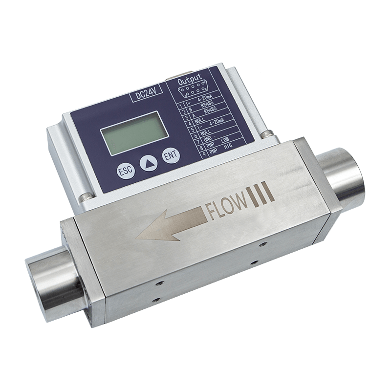
Both mechanical formats are generally available with the same range of output options, so the choice between inline and insertion rarely limits how the meter talks to the rest of a control system. A basic analog current loop remains common for straightforward monitoring, while a digital communication protocol suits installations feeding a central data historian or an energy management dashboard. Local displays are worth specifying whenever the meter sits somewhere a technician will actually walk past, since an on-unit reading often catches an anomaly long before it shows up in a trend report upstream.
It is also worth confirming whether the instrument offers a totalizer output in addition to instantaneous flow. For compressed air cost allocation between departments or production lines, a running total is frequently more useful day to day than the live rate, and retrofitting that capability after installation is rarely as simple as it sounds.
Comparing Performance Metrics Across Flow Technologies
Selection conversations tend to focus on three numbers: turndown ratio, typical accuracy, and permanent pressure loss. Thermal mass technology performs strongly on the first two and essentially removes the third from consideration, which is why it keeps displacing older orifice and pitot-based instruments in compressed air and gas monitoring retrofits.
Figure 2: Typical Turndown Ratio by Flow Technology
Wide turndown matters because plant demand rarely sits at one steady rate. Compressed air use swings through shift changes, weekend idle periods, and seasonal production shifts. A meter that only holds accuracy across a narrow band will misreport during the low-flow hours that often reveal leaks or waste, which is exactly when accurate data is most valuable.
Weighing Thermal Mass Against Vortex Shedding Meters
Vortex meters remain common on steam and higher-velocity gas lines, so it is worth comparing the two head to head across the factors that usually decide a specification. Neither technology is universally better; the right choice depends on flow velocity range, pipe size, and how much low-flow visibility a process actually needs.
Figure 3: Thermal Mass vs Vortex Meter, Five Selection Factors
Vortex meters generally hold an edge in higher-velocity steam and liquid-adjacent gas duties, but thermal mass technology pulls ahead on low-flow sensitivity and turndown, which explains why it dominates compressed air auditing, leak detection, and variable-demand nitrogen systems.
Mechanical construction is another point worth weighing. A vortex meter relies on a shedder bar interrupting the flow to generate a repeatable frequency, and that bar has to be sized correctly for the expected velocity range or the signal becomes unreliable at the low end. A thermal mass sensor has no moving parts and no minimum velocity threshold in the same sense, which is part of why it continues to register meaningful readings well into the flow rates where a vortex meter's signal starts to flatten out or drop below its usable range.
Calibration Strategy and Long-Term Reading Stability
Every thermal mass flow meter is calibrated against a known gas composition, typically dry air or nitrogen for general industrial use, and that calibration is what makes direct mass output possible without an external computer. Two practical issues shape long-term accuracy: gas composition drift away from the calibration reference, and sensor fouling from oil carryover or particulate in the stream.
Figure 4: Reading Drift Over a Twenty-Four Month Service Interval
The pattern above is illustrative, not a guaranteed curve, but it reflects a common field observation: drift accelerates once a thin film begins to insulate the heated element, since that film slows the heat transfer the sensor depends on. A recalibration or cleaning cycle every twelve to eighteen months is a reasonable default for compressed air service, shortened to six to nine months where oil-lubricated compressors or particulate-heavy gas streams are involved.
Some sensor designs also support field verification through a built-in reference check, which confirms the heater and reference elements still respond correctly without pulling the probe for a full bench calibration. That capability is worth asking about specifically if the application involves a hard-to-access insertion point.
Budgeting for calibration should be part of the original purchase decision rather than an afterthought once the meter is already running. Removable insertion probes and inline bodies with isolation valves allow a sensor to be pulled for cleaning or bench recalibration without shutting down the entire line, which matters a great deal on continuous processes where an unplanned outage carries a real cost. Where isolation is not practical, it is worth planning calibration windows around scheduled maintenance shutdowns so the instrument is never left running uncorrected for an extended stretch after drift has started to accumulate.
Application Fit Across Gas Types and Line Conditions
Not every gas behaves the same way against a heated sensor, and application fit deserves its own look before finalizing a specification.
Figure 5: Relative Suitability of Thermal Mass Measurement by Gas Service
Dry compressed air and inert gases sit closest to the original calibration reference, which is why plant-wide compressed air metering programs and nitrogen purge monitoring are two of the strongest fits for this technology. Variable-composition gases such as biogas introduce a real complication: the calibration is tied to a specific molecular makeup, so shifts in methane content will bias the reading unless the instrument includes a compensation table for that gas family. Wet or oil-carryover air is workable, but it pushes maintenance intervals shorter and rewards designs with self-cleaning or coated sensor tips.
When a facility runs more than one gas service, it is worth resisting the temptation to standardize on a single sensor configuration across all of them purely for procurement simplicity. A configuration tuned for dry nitrogen will not necessarily hold its rated accuracy on a humid compressed air header, and the small cost difference between a general-purpose sensor and one matched to each specific service is usually recovered quickly through fewer unplanned recalibrations.
Installation Practices That Protect Reading Accuracy
A thermal mass flow meter is only as good as the flow profile it sees. Two installation habits cause more field complaints than any sensor defect: insufficient straight-run distance and probe misalignment against flow direction.
- Provide the straight-run distance specified for the fitting in use, typically longer upstream than downstream, and increase it further after elbows, valves, or reducers.
- Align the sensor tip precisely against the direction of flow; even a small angular offset skews the velocity the sensor actually samples.
- Avoid mounting directly downstream of a control valve or regulator, where turbulence has not yet settled into a repeatable profile.
- For insertion designs, confirm insertion depth against the pipe centerline calculation rather than a generic depth setting.
- Route cabling away from variable-frequency drives and other high-noise electrical equipment to protect the low-level sensor signal.
- Verify orientation on outdoor or unheated lines, since condensation pooling around a horizontally mounted sensor can distort readings on humid gas streams.
None of these steps involve unusual tooling or specialized skill, but skipping any one of them is a common reason a newly commissioned meter reads plausibly but not accurately.
It also helps to document the as-built installation details at commissioning: actual straight-run lengths, insertion depth, cable routing, and orientation. When a reading later looks questionable, having that record on hand narrows troubleshooting to a short list of likely causes instead of starting an investigation from nothing. Many plants that run recurring compressed air audits keep this documentation alongside the calibration certificate for exactly that reason.
A Practical Selection Checklist
Bringing the previous sections together, a working specification for a thermal gas mass flow meter should answer each of the following before a purchase order goes out.
- Confirm actual pipe or duct diameter and whether an inline body or insertion probe fits the installation access.
- Document the gas composition, including moisture content and any oil carryover risk from upstream compressors.
- Define the expected minimum and maximum flow rates, then check that range against the meter turndown rating.
- Check available straight-run distance on both sides of the proposed mounting point.
- Decide whether local display, analog output, or digital communication fits the existing control system.
- Set a realistic calibration interval based on gas cleanliness rather than a generic default.
- Confirm the housing rating matches the installation environment, particularly for outdoor or washdown areas.
Working through this list before specification avoids the two most expensive outcomes in flow instrumentation: undersizing a meter that cannot cover peak demand, or oversizing one that never resolves the low-flow leak detection a plant actually needed. Treating the checklist as a short conversation between the process team, the maintenance team, and whoever manages the control system budget tends to surface constraints that a single department would miss on its own, particularly around cabling routes, isolation valve availability, and how the resulting data will actually be reviewed once the meter is in service.
Frequently Asked Questions
Q1: How accurate is a thermal gas mass flow meter compared to other technologies?
Typical accuracy sits within a small percentage of reading across most of the calibrated range, which is competitive with vortex and turbine designs while covering a wider flow range without recalibration. The main variable that moves this number in practice is how closely the actual process gas matches the composition the sensor was calibrated against, which is why documenting gas composition up front matters as much as the published accuracy specification itself.
Q2: Can a thermal mass flow meter be used on wet or saturated gas?
It can, but sustained moisture or oil carryover shortens the interval between cleanings, since any film on the sensor slows the heat transfer the measurement depends on.
Q3: Is an insertion or inline design better for compressed air metering?
Small branch lines generally favor an inline body for repeatable calibration, while large headers and main distribution lines are usually better served by an insertion probe sized to the pipe diameter.
Q4: How often should a thermal mass flow meter be recalibrated?
Twelve to eighteen months is a common baseline for clean, dry gas service, shortened to six to nine months where oil-lubricated compressors or particulate loading are present.
Q5: Does gas composition affect the reading accuracy?
Yes. The instrument is calibrated against a specific gas or gas family, so a meaningful shift in composition, such as variable methane content in biogas, requires a matched compensation table to stay accurate. Applications with a genuinely unpredictable gas mixture may need periodic laboratory sampling alongside the meter reading until enough data exists to confirm the compensation table is still tracking real conditions.
Q6: What causes a newly installed meter to read incorrectly from day one?
Insufficient straight-run distance and sensor misalignment against flow direction are the two most common installation errors, followed by mounting too close to a control valve or elbow.