

Eighty-four busbar joints, one switchgear room, and four different sensor models on the same quote sheet. That is how most wireless temperature monitoring projects start — and where many of them quietly go wrong. A joint sitting at 65 °C in normal operation can pass 120 °C in a single shift once a connection loosens, so the sensor must be cheap enough to install in volume, accurate enough to trust, and alive long enough to be useful.
The short version, before the detail: choose the measurement point first, the radio second, and the sensor model third. Accuracy class, battery chemistry, housing, and gateway count all follow from those three decisions. Work the other way around and you end up replacing batteries early, missing alarms, or buying a second gateway.
Quick answer: define the surface and the temperature excursion you must catch, confirm whether the point is energized, vibrating, or washed down, then pick a radio that reaches your gateway through metal. Only then compare sensors on accuracy, battery life at your real reporting interval, IP rating, and calibration support.
Start With the Measurement Point, Not the Sensor Catalog
A sensor that works on a cold-room wall will fail on an energized busbar. Before opening any catalog, write down five facts for every point on the list:
- Surface material and shape — copper bar, stainless pipe, painted steel, or open air.
- Normal range plus the excursion you must catch, not just the steady-state value.
- Whether the point is energized, rotating, or moving; that alone decides isolation and mounting method.
- How fast a change must be detected — seconds for a bearing, minutes for a cold room.
- Whether a technician can reach the sensor to replace a battery without a shutdown.
| Measurement point | Form factor that fits | Typical failure mode |
|---|---|---|
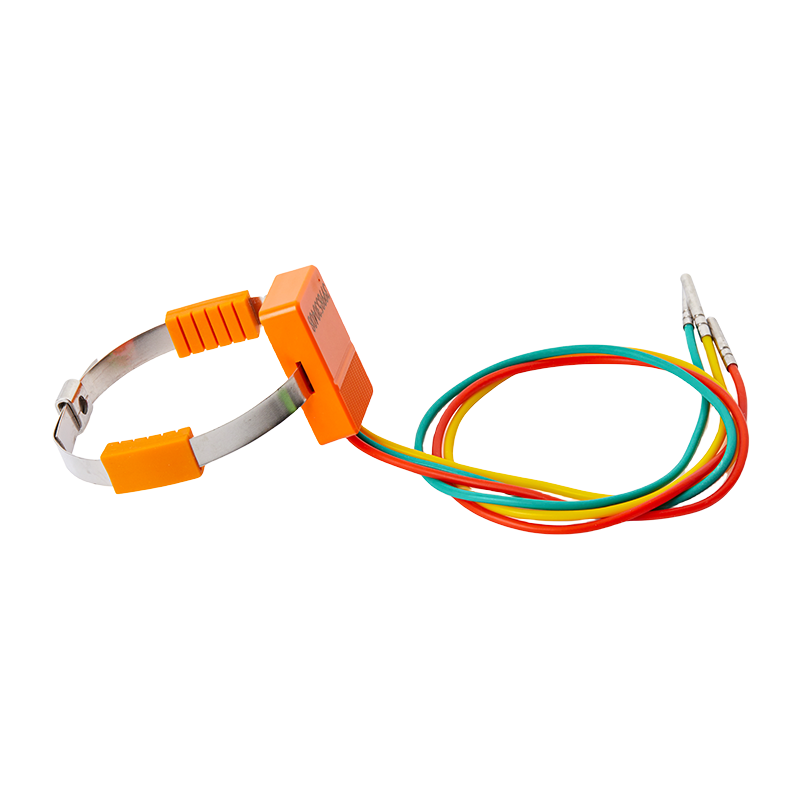
| Switchgear busbar, cable joint | Copper-plate or bolt-on contact sensor | Poor surface coupling; reads 10–20 °C low |
| Motor, pump, gearbox housing | Bolt-on probe or combined temperature and vibration sensor | Vibration loosens the mount; thermal lag hides spikes |
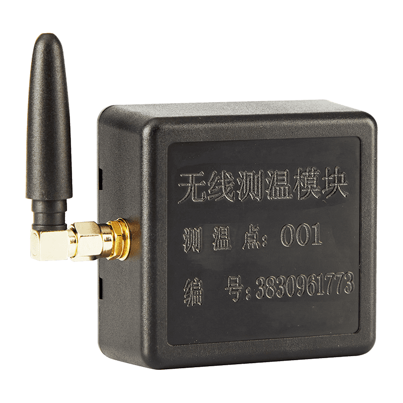
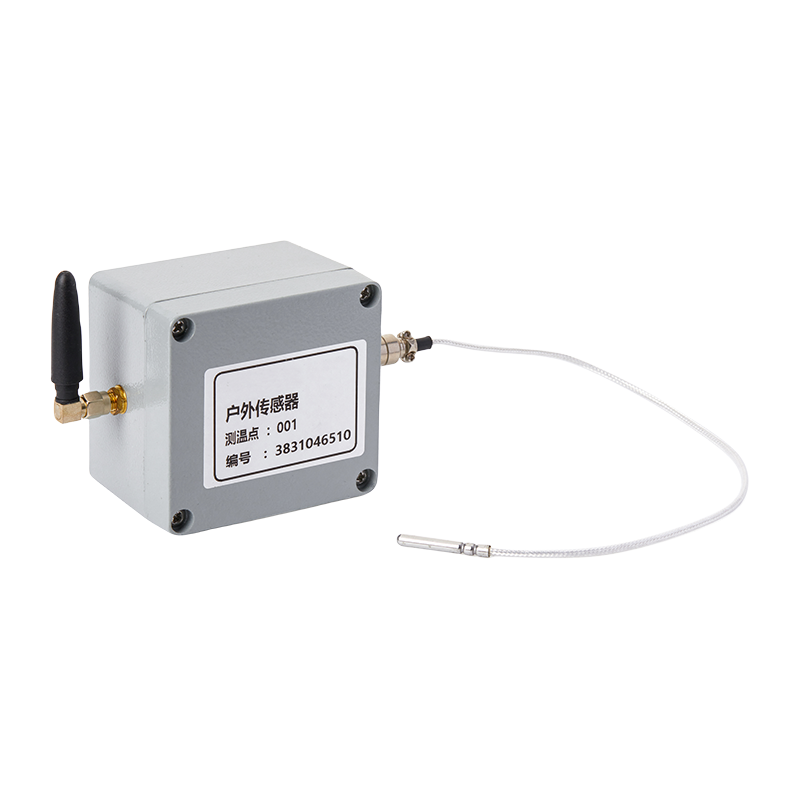
| Metal rail, conveyor track, pipe run | Long-range LoRa transmitter, magnetic or screw mount | Nearby metal shortens radio range |
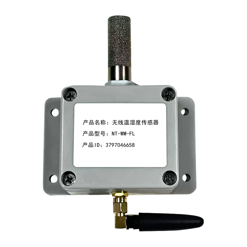
| Cold room, duct, cleanroom | Wall-mount temperature and humidity sensor | Condensation; IP rating below the washdown routine |
| Rotating or sealed equipment | Non-contact infrared | Emissivity error, blocked line of sight |
For busbar stubs, cable terminations, and switchgear contacts, a copper-plate sensor such as the KLDS33YS is bolted flat against the conductor so heat travels through metal instead of across an air gap. That single mechanical detail often decides whether the readings are worth logging.
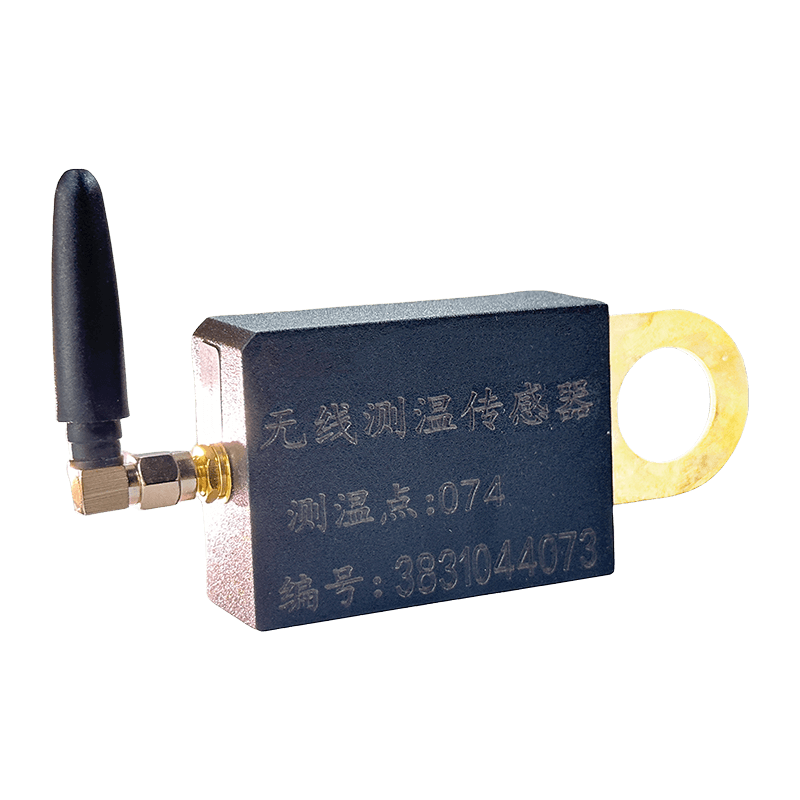 KL-DS33YS Copper Plate Wireless Temperature Sensor for Switchgear ContactsBolts flat against busbar and switchgear conductors, using LoRa wireless transmission and IP68 protection to monitor contact temperatures in high-voltage equipment.View Product →
Match the Radio to the Plant, Not the Datasheet Range
Radio figures are measured in open air. A plant is racking, steel walls, and hundreds of kilowatts of switching noise.
LoRa / sub-GHz 2.4 GHz NB-IoT / LTE-M
- LoRa and other sub-GHz bands (433, 868, 915 MHz): 1–5 km in open space, a few hundred metres through racking, hundreds of nodes per gateway, and the lowest draw for slow reporting.
- 2.4 GHz, including mesh topologies: faster response and higher throughput, but shorter reach and constant competition with Wi-Fi and Bluetooth in a crowded band.
- NB-IoT and LTE-M: no gateway to install, but a subscription per sensor, higher transmit power, and coverage that can vanish inside a steel building.
How many gateways will you need?
Budget one concentrator per 60–100 nodes, and fewer in dense metal, basements, and furnace areas. If your team is still weighing cable against radio, settle how wireless and wired temperature monitoring differ before shortlisting models, because the answer changes the mounting method and the power source.
Battery Life Is a Duty-Cycle Calculation, Not a Datasheet Number
A five-year battery is a bundle of assumptions: one reading every five minutes, 25 °C ambient, no failed transmissions, no mesh routing. Move any one of them and the number collapses.
- Temperature derating. At −20 °C a lithium cell delivers roughly half its rated capacity, and continuous operation above 60 °C accelerates self-discharge.
- Reporting interval. Halving the interval roughly doubles consumption; a one-minute interval can turn five years into eighteen months.
- Retries and hopping. Every failed packet and every relay hop can cost as much energy as hours of idle listening.
Ask for a consumption budget in microamp-hours per report rather than a headline year figure, and confirm whether the cell is field-replaceable. If it is sealed, budget replacement cost from day one.
A sensor rated for five years at a five-minute interval is a two-year sensor at a one-minute interval. Set the interval from the process, then buy the battery that survives it.
Separate Sensor Accuracy from System Accuracy
A ±0.5 °C figure on a datasheet describes the sensing element under reference conditions. The value your SCADA records also includes the probe, the mounting contact, the conversion electronics, and the calibration state.
- Element class. A Pt100 class A element is roughly ±(0.15 + 0.002 × |t|) °C, while many digital IC sensors are quoted at ±0.5 °C across the full range.
- Mounting error. A probe clipped to a pipe with poor contact can read 10–20 °C below the true surface temperature, which is larger than any element-grade difference.
- Drift and recalibration. Plan on 12–24 month intervals, with a traceable certificate from an accredited calibration laboratory.
When the driver is an audit — food safety, pharmaceutical cold chain, or a customer quality agreement — alarm logs, timestamp integrity, and calibration records matter more than a 0.2 °C gain in element accuracy. Buy the record-keeping first.
Environmental Ratings, Mounting, and the 20 °C Error Nobody Checks
Four things end wireless deployments early: water, vibration, ambient heat, and radio-blocking metal.
- Ingress protection. IP65 is the floor for a dusty plant; specify IP67 where washdown or condensation is routine.
- Housing ambient limit. Check the transmitter rating, not only the probe. A 60 °C cabinet will exceed electronics rated to 55 °C.
- Vibration. Brackets loosen and solder joints crack. On motors and gearboxes, a combined temperature and vibration sensor such as the KLWZ35LQ captures both signals from one installation point.
- Antenna placement. An antenna inside a closed metal enclosure loses most of its range; mount the transmitter outside the cabinet or use a remote antenna.
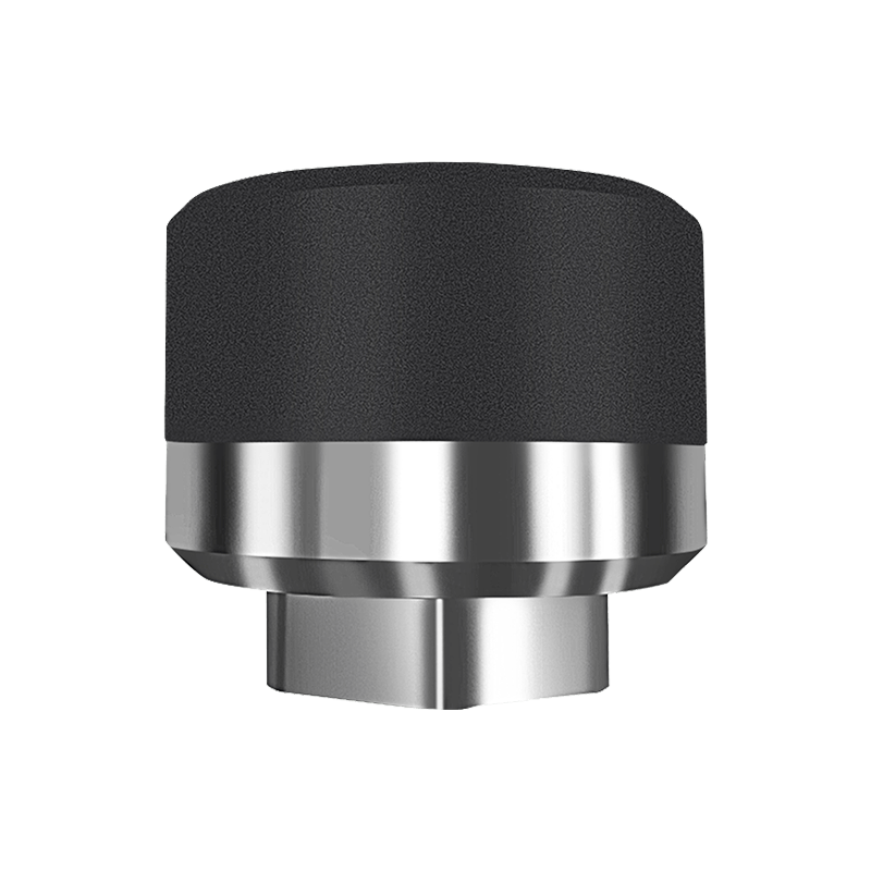 KL-WZ35LQ Three-Axis Wireless Temperature and Vibration SensorFor motors, fans, and pumps, it combines triaxial vibration and temperature monitoring over LoRa in an IP65 enclosure; verify hazardous-area certification separately.View Product →
In explosive atmospheres, intrinsic safety certification decides the model before any specification comparison begins.
Plan the Route from Sensor to SCADA
Wireless ends at the gateway, and the gateway is where projects stall. Confirm three points before ordering:
- Node capacity and local buffering — the host should hold readings when the uplink drops and forward them with original timestamps.
- Northbound protocol — Modbus TCP, MQTT, or OPC UA. Match what the controls team already runs.
- Where alarms live — threshold logic at the host keeps working when the cloud link does not.
A monitoring host such as the KLMT86MP is sized for plant-floor collection and forwarding. Where pulling new Ethernet cable is impractical, power-line communication modules can carry the same data over existing power wiring and keep the gateway count down.
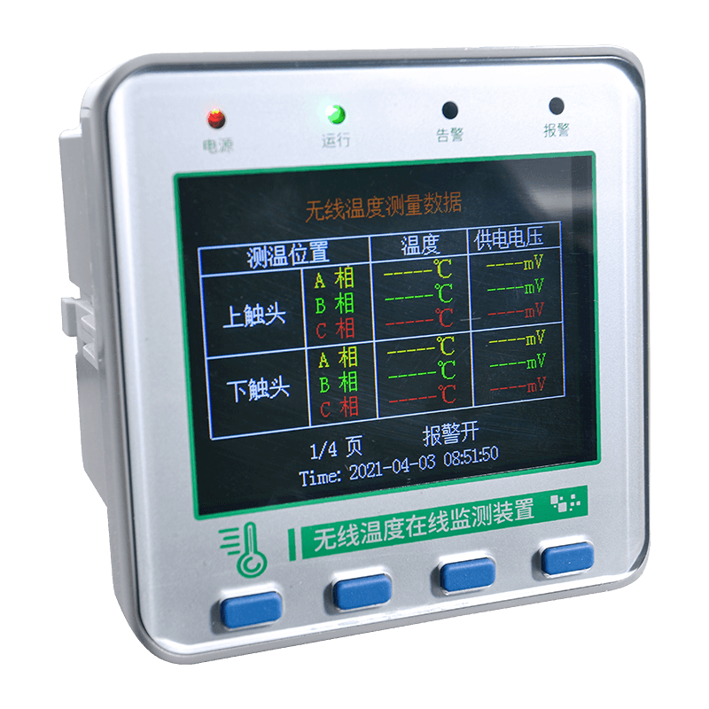 KL-MT86MP Color Screen Wireless Temperature Measurement HostCollects wireless sensor data for high-voltage equipment, offering color display, RS485/Modbus output, and alarm relays for plant-floor temperature monitoring.View Product →
A Short Checklist Before You Order Samples
- Run one sample unit at your real reporting interval for two weeks, inside the real cabinet.
- Request the link budget, plus a walk test if the plant is dense with metal.
- Confirm the calibration certificate, its traceability, and the recommended recalibration interval.
- Check the battery type, its replacement procedure, and the tools it needs.
- Verify node capacity, buffering, and northbound protocol on the host, then agree spare parts and warranty in writing.
Frequently Asked Questions
Q1: How many wireless temperature sensors can one gateway support?
Plan on 60–100 nodes per gateway in a typical plant, and fewer where steel structures, basements, or high-power equipment block the path. A walk test with a sample node gives a firmer number than any datasheet.
Q2: Is a wireless sensor accurate enough for compliance records?
Yes, provided the whole measurement chain is calibrated and readings are logged with reliable timestamps. The element is rarely the limiting factor; mounting contact, recalibration intervals, and audit logs usually are.
Q3: Contact sensor or infrared?
Infrared suits points that cannot be touched, but emissivity, distance, and line of sight all add error. For a fixed point you can reach, a contact sensor delivers more repeatable data.
Q4: What reporting interval should we set?
The shortest interval that still leaves a comfortable battery margin. Bearing monitoring may need one reading per minute; busbar joints and cold rooms are usually fine at five to fifteen minutes, with threshold-triggered reporting for fast excursions.
The Decision, in One Line
Choosing a wireless temperature sensor is a measurement decision rather than a shopping decision: map the points, pick the radio that reaches, size the battery for your real interval, and confirm the calibration path. The model list shortens quickly once those four answers exist.
ASY Electronics builds exactly that layer of the stack — wireless temperature, humidity, and combined temperature-vibration sensors, monitoring hosts, and the industrial communication modules that connect them. The hardware comes out of a 5,000 m² workshop backed by more than 20 years of electronics manufacturing experience.
Send us your point list — surface, temperature range, and reporting interval — and our engineers will shortlist the sensor, host, and radio combination that fits the job. Browse the wireless temperature monitoring range, or start with a pilot installation in one cabinet before rolling out plant-wide.