

A retrofit crew walks into a three-phase MCC room with a job that sounds simple: pull Modbus TCP data from eleven inverter-fed motors back to the control room. Then they look at the cable trays. Every conduit is full, the nearest managed switch is 180 m away, and production cannot stop for a cable pull. The power conductors, however, are already there.
That is the job H-PLC (high-speed power line communication) is built for, and it is also where projects stall. The modem is rarely the weak point. The architecture around it is.
The conclusion first: an H-PLC communication system architecture is five cooperating layers. A coupling and boundary layer conditions the mains; a PHY layer modulates the carrier; a MAC layer arbitrates access to a shared medium; a network and transport layer makes the segment behave like ordinary Ethernet; an application layer hosts sensors, controllers and telephone endpoints. Two of the five decide whether a link survives a year of production — the boundary layer and the MAC layer.
Working rule: design the boundary first, the network second, and choose the modem last.
The Five Layers of an H-PLC Architecture at a Glance
Every deployment, from a point-to-point link between two panels to a plant-wide network with dozens of domains, contains the same five layers. Only the boundaries between them change.
Read the stack from the bottom up. A sensor produces a value, the network layer wraps it in an IP packet, the MAC layer schedules the transmission, the PHY layer modulates it onto the mains, and the boundary layer keeps that signal inside the domain where it belongs. A fault at any layer looks the same on the SCADA screen: a tag that stops updating.
Wavelet OFDMTDMA / CSMAIEEE 1901IEEE 1905.1AES-128
Coupling and the Boundary Layer: Where Installations Are Won or Lost
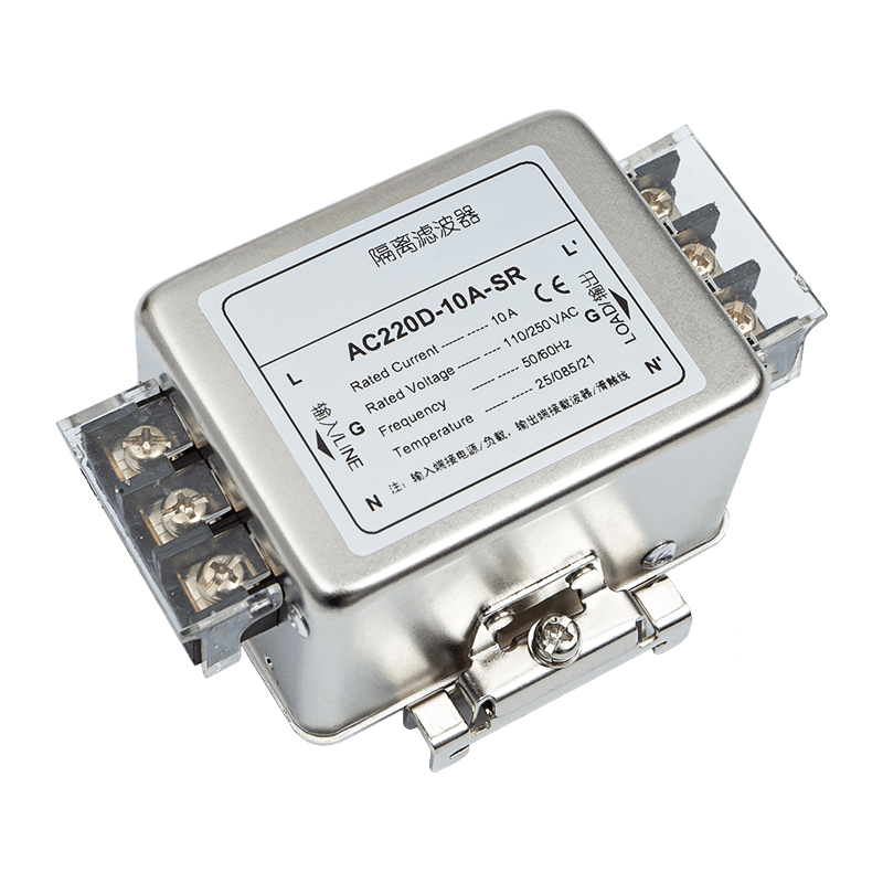
On a schematic the mains look like two clean conductors. In a running plant they are a transmission line with a shifting impedance, a noise source, and an antenna. Inverter switching edges, soft starters, contactor arcs and switched-mode supplies all inject energy into the band the carrier occupies. The boundary layer makes that environment survivable: couplers inject and extract the carrier without exposing the modem to mains voltage, isolation filters keep the signal inside its own domain, and phase couplers carry it across conductors that are not galvanically joined.
Why the isolation filter is the part nobody should skip
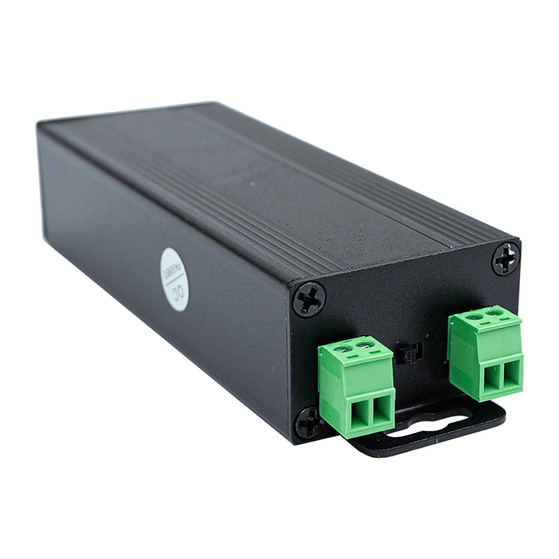
Leaving out the isolation filter is the most common and most expensive shortcut in H-PLC work. Without it, the signal travels along the incoming feed into neighbouring domains, two separate networks merge into one, and a load switched on in the next building can take an unrelated production line offline. The filter belongs at the edge — the transformer or the incoming feed — where it terminates the domain. Isolation filter models such as the AC3803D are built for exactly that position, so the network ends where the drawing says it ends.
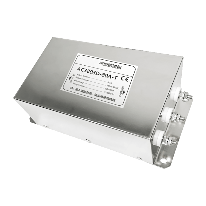 AC3803D Three-Phase Three-Wire Isolation Filter for Power Line CarrierAt the transformer or incoming feed, this filter terminates the PLC domain, preventing signal leakage into neighbouring networks and ensuring the network ends as intended.View Product →
Phase coupling in three-phase distribution
A coupler on L1 is not automatically visible to a coupler on L3. Where nodes must talk across phases, the architecture needs capacitive phase couplers or a dedicated coupling unit that bridges them. Skipping that step produces the most confusing symptom in H-PLC work: half of the network online, half permanently offline, and nothing in the log that points at the wiring.
Impedance, stubs and reflections
Line impedance swings with load, so coupling capacitance and termination should be matched to a range rather than tuned to a single measurement. Short unterminated branches reflect energy and push the modem toward a lower modulation order; keeping stubs short is usually cheaper than adding a repeater later.
Measurements worth taking before any hardware is ordered
- Noise floor with drives stopped, then with drives running under load.
- Attenuation between the two endpoints furthest apart, measured through the real couplers.
- Cross-phase attenuation between domains that must stay separate.
- The point where the domain should be terminated, and the filter that fits it.
PHY and MAC Layers: Modulation, Retransmission, and Encryption
Once the channel is conditioned, the PHY layer has a job it can actually do. HD-PLC class devices use wavelet OFDM, spreading the payload across many narrow subcarriers in a wide frequency range — roughly 2 to 30 MHz in the HD-PLC profile — and adjusting modulation depth per subcarrier as the channel changes. Subcarriers hammered by drive harmonics simply carry fewer bits, or are notched out, instead of dragging the whole link down. Link quality is therefore a curve, not a yes-or-no answer: a marginal run can deliver workable throughput at commissioning and fail the day a second drive is switched on. Signal integrity across noisy mains is a measurement task, not a purchasing decision.
The MAC layer works on a medium nobody owns. Industrial H-PLC implementations typically combine a scheduled access period for cyclic traffic with a contention period for everything else, acknowledge frames at the link layer, and retransmit automatically so a single corrupted frame never reaches the application. Two questions matter during specification: does the stack expose priority classes for control traffic, and is link encryption on by default? AES-128 link encryption is available in current HD-PLC silicon, and switching it off because the segment is "only internal" is a decision that tends to be revisited after the first security audit.
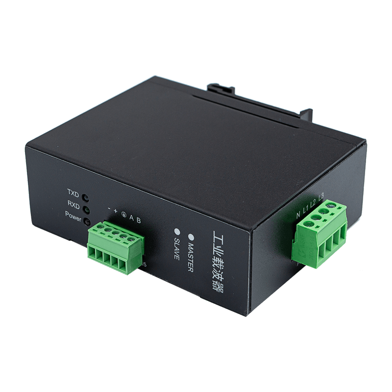
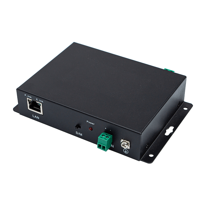
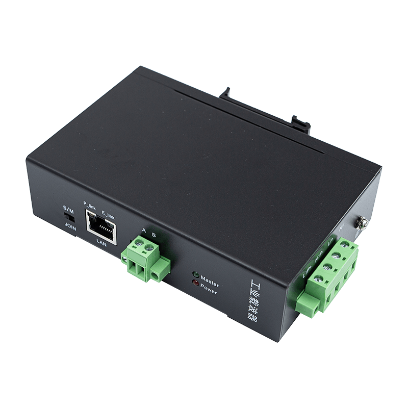
Modem hardware for this layer includes units such as the KS700M4P in the high-speed power line communication range; whichever model is specified, it should be selected after the channel measurements above, not before them.
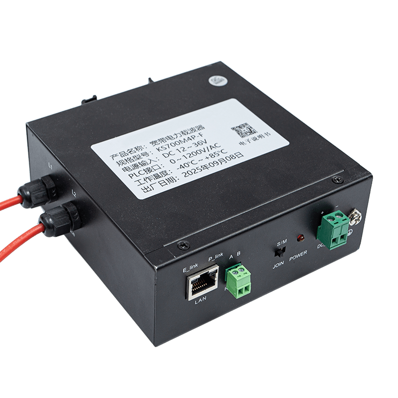 KS700M4P High-Voltage Broadband Powerline TransceiverTransceiver for high-speed PLC, supporting Ethernet and RS485 Modbus, with automatic networking and up to 1000 Mbps over power lines. Suitable for demanding industrial networks.View Product →
Network and Application Layers: Making the Segment Behave Like Ethernet
Between the MAC layer and your application sits the network layer, and that is where most integration pain appears — not in the mains. An H-PLC segment normally presents itself as a transparent Ethernet bridge, so Modbus TCP, OPC UA and BACnet/IP traffic pass through unmodified. That convenience cuts both ways: the bridge is transparent to loops and broadcast storms too. Give every PLC domain its own IP subnet and router boundary, keep Layer 2 loops out, and treat the segment as a link you own rather than a flat extension of the office LAN. Where wireless instrumentation already exists, IEEE 1905.1 defines how PLC, wireless and Ethernet are abstracted as one link layer so forwarding rules stay consistent.
Above that sits the application layer, where value is realised: temperature sensors on busbars and bearings, pressure and level transmitters, flow meters feeding energy accounting, and handsets that use the same power line for voice. A PLC digital telephone such as the CS618LFS220 is an endpoint inside this architecture, not a separate system bolted on beside it.
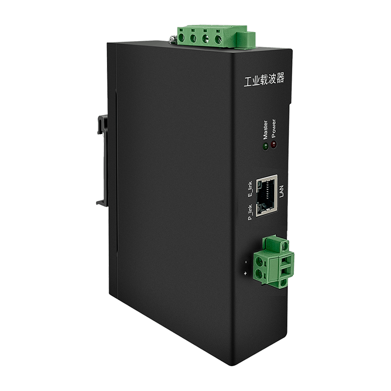 HD-PLC Industrial Power Line Communication Product RangeExplore a range of IEEE P1901-compliant HD-PLC devices for high-speed data over power lines, suitable for smart grids, robotics, and industrial automation.View Product →
Design Variables, Working Rules, and Failure Symptoms
Most H-PLC problems trace back to a handful of decisions that were never written down. The table below pairs each variable with a working rule and the symptom that shows up when the rule is ignored.
| Design variable | Working rule | Symptom when ignored |
|---|---|---|
| Utility boundary termination | Terminate every domain with an isolation filter at the incoming feed or transformer | Domains merge, throughput drops, unrelated loads disturb the link |
| Phase coverage | Bridge phases with couplers before commissioning, not after | Nodes on different phases stay permanently offline |
| Noise margin | Size the link against the noise floor measured with production running | Stable during commissioning, unstable during the day shift |
| Domain size | Split by function into smaller domains instead of stretching one | Rising retransmissions and unpredictable latency |
| Traffic priority | Separate or prioritise cyclic control traffic over bulk transfers | Control writes queue behind firmware uploads |
| Topology | Keep stubs short and avoid long runs into unused areas | The link negotiates a lower modulation order and fluctuates |
Common Architecture Mistakes to Avoid
- Treating the mains as a cable with predictable impedance.
- Sharing one domain between control traffic and camera or bulk data.
- Assuming all three phases are automatically connected.
- Omitting the isolation filter because a bench trial "worked fine".
- Commissioning with production stopped and never repeating the test under load.
FAQ: H-PLC Architecture Questions Engineers Ask
Q1: What separates H-PLC from the narrowband PLC used for metering?
Narrowband PLC works in the kHz range at low data rates, which suits meter reads but struggles with TCP/IP control traffic. H-PLC uses a wide MHz band with wavelet OFDM, delivering megabit-class throughput and latency low enough for cyclic control. Both are power line communication; only one carries an Ethernet-shaped workload comfortably.
Standards do not set a practical ceiling — traffic does. Group ten to thirty nodes with similar traffic profiles per domain, keep camera feeds and bulk transfers in their own domain, and split further with filters rather than stretching one domain across a whole plant.
Q3: Does an H-PLC network need its own cabling?
No dedicated communication cable is required, which is the point of the technology. What is required is a continuous copper path between nodes: a transformer, an open breaker, or a missing filter between two sides of the network will stop the signal regardless of how good the modem is.
The architecture decides the outcome. Terminate each domain at its boundary, bridge the phases deliberately, measure the noise floor with production running, and keep the network layer as disciplined as you would any wide-area link. Do that and H-PLC behaves like the cable you never had to pull.
ASY Electronics supplies the hardware that fills these layers — coupling and filtering components, H-PLC modems, wireless temperature monitoring systems, transmitters and bus-mounted sensors — and supports the integration work around them. If your next retrofit starts in a crowded conduit, talk through your architecture with our engineers before the bill of materials is fixed.